The information in this article applies to:

QUESTION
I have imported a DWG or DXF file and would like to convert the 2D lines to 3D objects such as walls, doors and windows. How can I accomplish this task using the CAD to Walls tool?
ANSWER
The CAD to Walls tool can be used to convert CAD lines in floor plan view into 3D architectural objects. Two or more parallel CAD lines can be converted to both straight or curved walls or railings. CAD lines representing windows and doors can also be converted.
To import a DWG/DXF file
- Launch Chief Architect and start a New Plan
 .
.
- Select File> Import> Import Drawing (DWG, DXF)
 from the menu.
- In the Import Drawing Assistant dialog that displays, click Next or Continue to go to the Select File portion of the dialog:
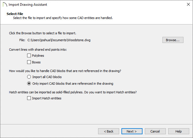
- Use the Browse button to browse to the DWG or DXF file's location on the computer, select it, then click the Open button.
- Do not check Polylines or Boxes under the Convert lines with shared end points section at this time.
- Click Next or Continue.
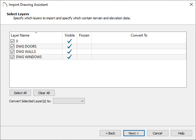
- On the Select Layers portion of the dialog:
-
Check all of the layers that you want to import on the left
-
The Convert Selected Layer(s) drop-down menu allows you to convert the data on any layer into a Terrain Perimeter or Elevation Data.
For more information on this topic, please visit the "Importing Terrain Elevation Data from a DXF or DWG File" resource located in the Related Articles section below.
-
Click Next or Continue.
-
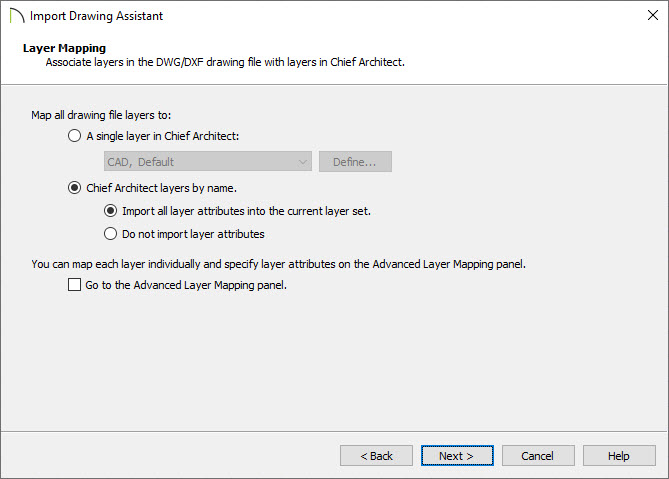
Under Layer Mapping:
-
Move the radio button to Chief Architect layers by name.
-
Click Next or Continue.
-
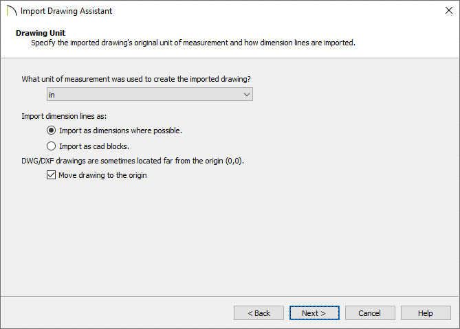
Under Drawing Unit:
-
Select a unit of measurement from the drop-down list.
-
Check the Move drawing to the origin box to center it in your plan.
- Click Next or Continue.
-
Click Finish or Done to bring the DWG or DXF drawing in to your floor plan.
After your 2D CAD drawing has been imported into Chief Architect, you may want to make some additional adjustments to their locations. For best results, delete any wall lines or polylines located between interior and exterior wall surface lines. When CAD objects are located properly, you are ready to use the CAD to Walls tool.
To use CAD to Walls
- Select CAD> CAD to Walls
 to display the Convert CAD to Walls dialog.
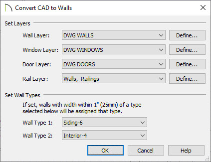
- Specify the source layers to be converted to walls, windows, doors, or rails.
It's recommended that lines representing windows and doors are not defined/associated as CAD blocks, and are on different layers.
Arcs indicating door swings help to identify a door, and as such, should be placed onto the same layer as doors.
- Specify wall types for the new walls.
To convert CAD lines to a specific wall type, the lines must be within one inch (or 25mm) of that wall type’s width.
If the distance between the surface lines is less than the total width of the specified wall type, a copy of that wall type will be created. The width of its Main Layer will adjust so that the overall width is equal to the specified wall’s Main Layer.
- Click OK to complete the conversion.
- Create a Camera
 view to see the results.
- You can now further customize the walls, doors and windows created by the CAD to Walls tool, as well as specify Room Types, create cabinets and terrain, and place objects from the Library Browser.