The information in this article applies to:

QUESTION
How can I create a tray ceiling?

ANSWER
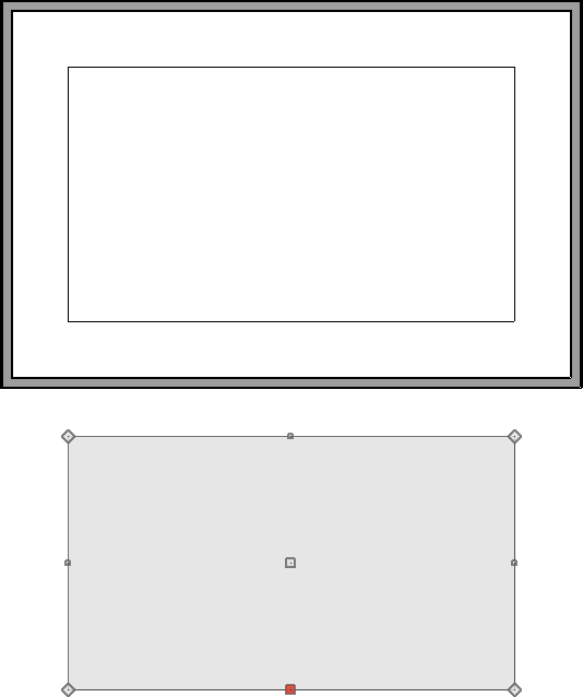
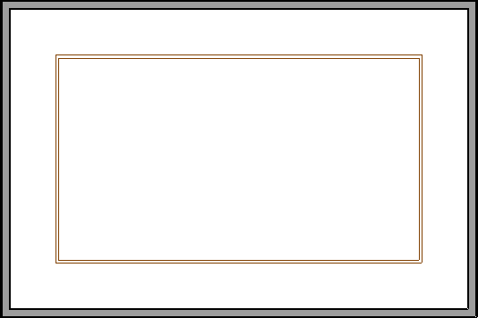
A tray ceiling is a raised area in the middle of a room that takes advantage of the attic space above the room. It can be as simple as a vault that follows the roof line to a flat raised area or something more elegant that takes advantage of moldings to decorate the edges of the raised area. We will explain two methods to create tray ceilings in Chief Architect:
To create a tray ceiling using tray ceiling polylines
*Applies to Chief Architect X12 and newer program versions.
-
Open
 the plan you would like to create a tray ceiling in.
- Navigate to Build> Roof> Tray Ceiling Polyline
 and with the tool selected, left-click and drag inside of the room you would like to create your tray ceiling in.
Alternatively, you can click inside of a room to select it and select the Make Tray Ceiling in Room  edit tool.
- Much like other polyline-based objects, each edge of the newly created ceiling plane can be modified.
- The Break Line
 tool can be used to place break points and create new edges.
-
Fillet Lines
 can be used to create a corner with a radius.
-
Chamfer Lines
 allows you to create a straight corner bevel.
- The Change Line/Arc
 tool can be used to convert straight lines to arcs.
- Once the shape of the tray ceiling plane is to your liking, select it using the Select Objects
 tool and click on the Open Object
  edit button.
- On the General panel of the Tray Ceiling Specification dialog that displays:
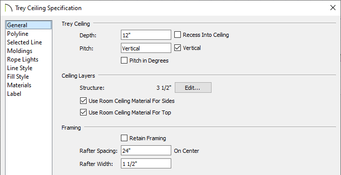
- Adjust the Depth of the tray. By default, this is set to 12".
- If the Make Tray Ceiling in Room edit button is used instead, you will have a Width option which allows you to specify how far inside of the room you would like the tray to start at. By default, this is set to 24".
- Check Recess Into Ceiling to build the outer ceiling at the room's specified ceiling height and raise the inner ceiling plane into the room's ceiling platform. When unchecked, the inner ceiling is positioned at the room's specified ceiling height and the outer ceiling is dropped.
- Specify the Pitch of the tray's sides if desired. When a non-vertical value is specified, a sloped ceiling plane is created along each edge of the tray. Check the Vertical box to produce vertical sides with no side ceiling planes.
- In Chief Architect Premier, you can also specify the Structure of the ceiling layers that make up the tray. Click Edit to modify the structure. Check Use Room Ceiling Material for Sides to apply the room's ceiling finish material to the sides of the tray. Check Use Room Ceiling Material for Top to apply the room's ceiling finish material to the top of the tray.
- Starting in X13, framing properties for the tray ceiling, such as the Rafter Spacing and Rafter Width, can also be specified. Use the Build Framing For Selected Object(s)
 edit tool to generate tray ceiling framing.
- On the Moldings panel, click the Add New button to add a molding profile to the tray ceiling.
- Specify the Width, Height, and Offsets of the molding profile.
- On the Rope Lights panel, click the Add New button to open the Rope Light Specification and specify your desired properties for rope lighting, then hit OK to return to the Tray Ceiling Specification dialog.
- Specify any desired Offsets for the rope lighting.
- Make any other changes to the tray ceiling polyline, such as the Fill Style or Materials, then click OK to confirm the changes and close the dialog.
The Hole in Floor Platform and Hole in Ceiling Platform tools will not cut through tray ceiling polylines.
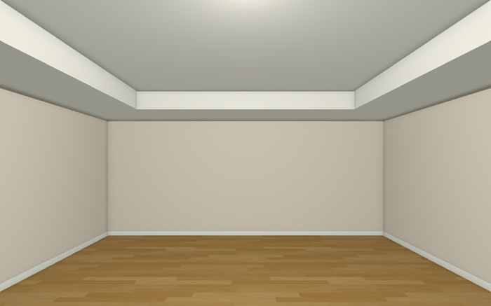
- Lastly, take a Camera
 view to see the results.
Nested tray ceilings and coffered ceilings can also be created using tray ceiling polylines. To learn more, access your software's documentation by navigating to Help> Launch Help.
Return to Top
Tray ceilings can also be created using the Platform Hole tool along with custom ceiling planes.
To create a tray ceiling using the platform hole tool
- Select Build> Floor> Hole in Ceiling Platform
 and with the tool selected, left-click and drag inside of the room you would like to create your tray ceiling in.
- With the hole created, proceed to use edit tools such as Break Line , Fillet Two Lines , Chamfer Two Lines , or Change Line/Arc to shape the platform hole as needed.
- Next, we will create the sides of the tray ceiling. To do this, click on the hole to select it, click the Copy/Paste
 edit button, then click in an empty area of the floor plan to place a copy of the platform hole polyline at that location.
In this example, the copy was placed below the main structure.
You may receive a warning that "A floor or ceiling platform hole polyline is placed where the platform height changes, or where no platform exists. Move the hole so it's completely contained within a single platform." If so, click OK.
- With the copied platform hole polyline selected, click the Convert to Plain Polyline
 edit button.
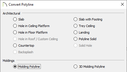
- Next, click the Convert Polyline
 edit tool and in the Convert Polyline dialog box that displays, select Molding Polyline, then click OK.
- In the Molding Polyline Specification dialog that displays next:
- On the General panel, specify the Height of the molding polyline.
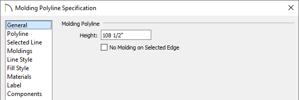
The height should be set to be the same value as the height of the room minus the ceiling finish material. In cases where a rooms height is set to be 109 1/8", the height of the molding polyline should be set to 108 1/2" to account for the 5/8" of ceiling drywall.
- On the Moldings panel, click the Add New button and browse the Select Library Object dialog to select a molding profile.
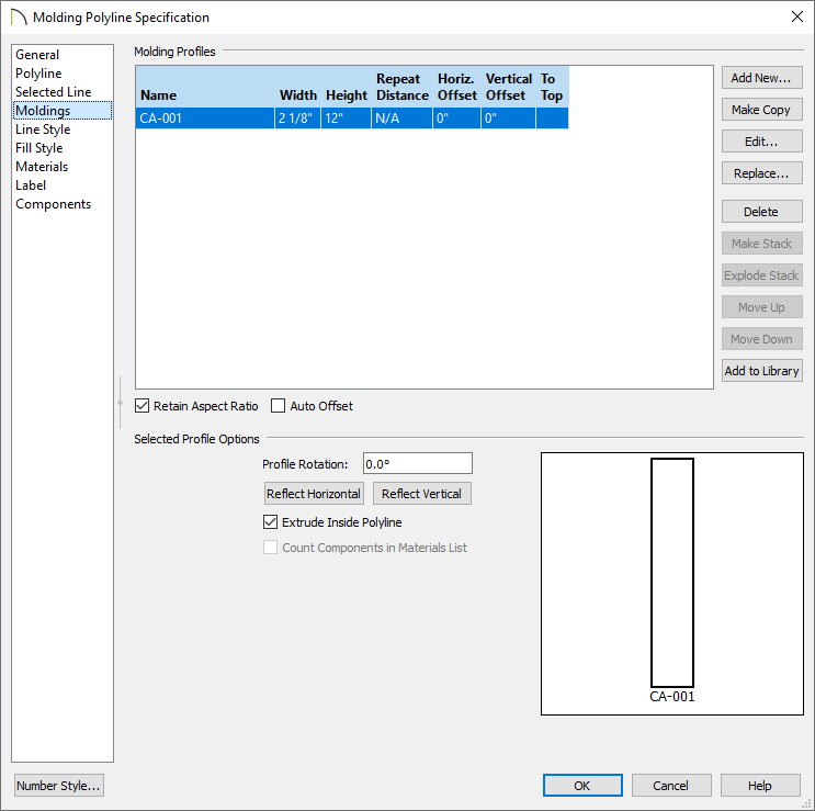
- Profiles can be found by navigating to Chief Architect Core Catalogs> Architectural> Moldings, Profiles, Extrusions.
In this example, the CA-001 profile was selected.
- Specify the Height and Width of the Molding Profile.
In this example, the Retain Aspect Ratio box was checked, and the Height was changed to 12" as that is going to be the depth of the tray once it is complete.
- Specify any Offsets and ensure that the Extrude Inside Polyline box is checked.
- Click OK to close the dialog box and apply your specifications to the molding polyline.
- Click on the molding polyline to select it and use the Move
 edit handle to move the polyline into the same location as the platform hole inside the room.
If you have difficulty aligning the molding polyline with the platform hole, consider using the Point to Point Move tool. More information on using this tool can be found in the Related Articles section below.
The platform hole and molding polyline should now be at the same location.
- Select Build> Roof> Ceiling Plane
 from the menu.
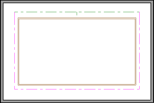
- Creating a ceiling plane is similar to manually creating a roof plane: click and drag to create the ceiling plane baseline, then release the mouse button;
- Then drag and click once to establish the location of the ceiling plane ridge.
- The ceiling plane displays with dashed pink lines and was drawn larger than the platform hole.
- Select the newly created ceiling plane, click the Open Object edit button to open the Ceiling Plane Specification, and on the General panel:
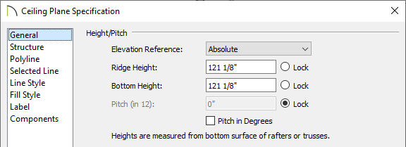
- Set the pitch to 0 to create a flat ceiling.
- Click the Lock radio button next to Pitch (in 12) to lock it.
- Raise the height of either the Ridge Height or Bottom Height.
In this example, the upper ceiling plane is 12 inches above the lower ceiling plane, so the value specified is 121 1/8".
- On the Structure panel of the same Ceiling Plane Specification dialog, uncheck Use Room Ceiling Finish, then hit OK to confirm the changes.
In Chief Architect Interiors, this checkbox is located on the General panel.
- Use the ceiling plane's edit handles to reshape the ceiling so that it is the same shape as the platform hole.
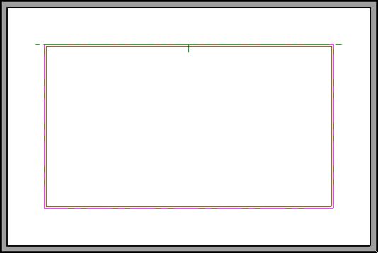
The platform hole, the molding polyline, and the custom ceiling plane should now all be in the same location.
- Finally, create a Camera view to see the results in 3D.