The information in this article applies to:

QUESTION
I would like to create a custom arch with a precise radius. What is the best way to do this?

ANSWER
The 3D Solid tool, which is named Polyline Solid in X13 prior versions, is a fast way to create custom 3D shapes; however, if you'd like to create a custom shape with arcs and precise dimensions, you may find it easier to use the CAD drawing tools to create a custom closed polyline, then convert it to a 3D/Polyline Solid using the Convert Polyline tool.
To precisely define an arc
- Select File> New Plan
 from the menu to create a new, blank plan.
- If you would like the curve of the arc to be oriented vertically, select 3D> Create Orthographic View> Cross Section/Elevation
 . Otherwise, remain in floor plan view.
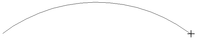
- Select CAD> Arcs> Draw Arc
 from the menu, then click and drag an arc of the approximate size needed.
- Click on the arc to select it, then click the Open Object
 edit button.
- On the Arc panel of the Arc Specification dialog, specify the desired attributes of the arc.
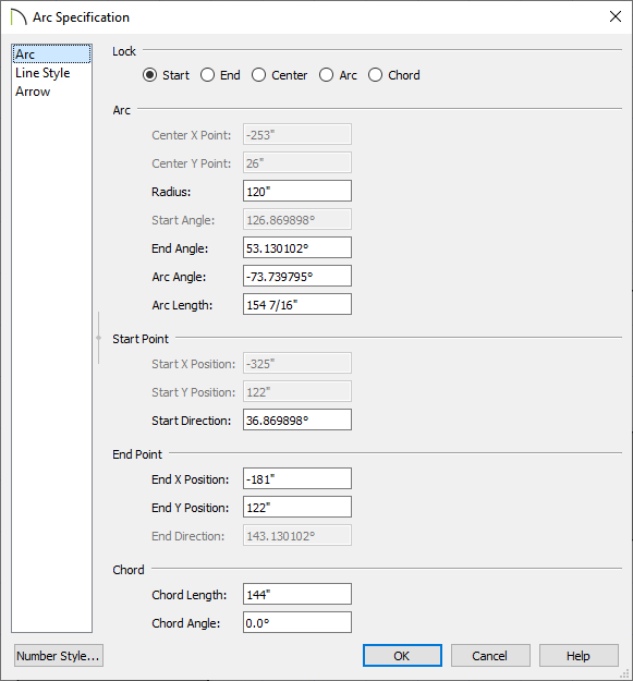
- The Start Y and End Y values should be the same; if they are not, lock either the Start or the End of the arc at the top of the dialog and change the value that is available for editing.
- With either the Start or the End still locked, specify the desired Radius of the arc, then press the Tab key on your keyboard to update the information in the dialog without closing it.
In this example, a radius of 120" is used.
- Specify the desired Chord Length, then press the Tab key.
In this example, we have chosen a value of 144" as the arc will be placed over a 12' opening.
- Click OK to close the dialog and apply your changes.
To create a closed 3D/Polyline Solid that includes the arc
Once the arc is defined and locked, we can add CAD lines to create a closed polyline and then convert it to a solid. Taking advantage of some CAD editing options will help us do this effectively.
- Click Edit> Snap Settings
 and make sure that Object Snaps
  and Endpoint
  snap settings are toggled on. This will allow us to precisely snap new lines to the ends of our arc.
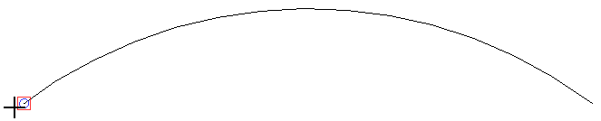
- Select CAD> Lines> Draw Line
 from the menu, then click and drag a line beginning at one end of the arc. Notice the square-shaped Endpoint snap indicator that displays where the line meets the arc.
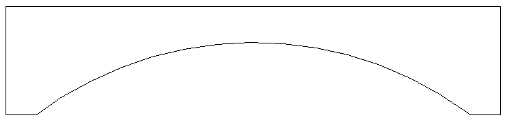
- Continue drawing and defining lines until you have created a closed polyline with the desired size and shape.
- Using the Select Objects
 tool, click on the polyline near one of its edges to select it, then click the Convert Polyline
  edit button.
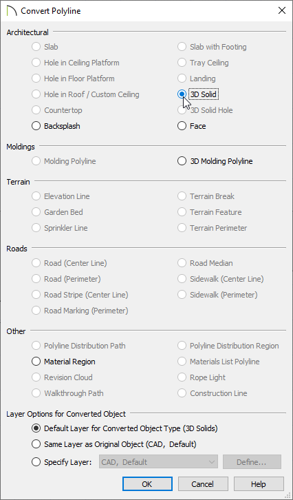
- In the Convert Polyline dialog that displays, select the 3D/Polyline Solid option, choose your preferred Layer Options, then click OK.
- In the 3D/Polyline Solid Specification dialog, which opens next:
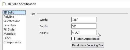
- On the General panel, specify the Height for the solid if you're in X14 or the Thickness if you're using X13 or a prior version.
For the purposes of this example, we specified a value of 4 1/2", which is the same thickness as our Interior-4 wall type.
- If the 3D/Polyline Solid was created horizontally, such as in a floor plan view, different values may need to be adjusted to get the desired result.
- On the Materials panel, select the 3D/Polyline solid component, click the Select Material button, then browse the library for a suitable material.
- Once all desired changes have been made, click OK to close the dialog(s).
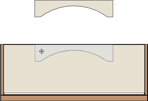
- The CAD polyline that you drew is now a custom 3D object.
- In many cases, you will want to draw your 3D/Polyline Solid in place; in this example, however, the solid was drawn in an empty space above the elevation to improve image clarity.
- It can now be selected and moved into place using the Move
 edit handle.
- Hold down the Ctrl/Command key on your keyboard to move an object such as the 3D/Polyline Solid through obstructions such as the ceiling as it's moved into place.
- If you'd like to center the solid on a particular wall, click on the solid to select it, select the Center Object
 edit button, then click on the wall once the perpendicular guidelines appear.
- Create a Camera
 view to see the results.
You can use the Trim tools to create manual casing around the custom shaped arched opening if you wish. The Trim tools can be located by navigating to Build> Trim from the menu.