The information in this article applies to:

QUESTION
How to create a post and beam structure in Chief Architect?

ANSWER
There are a wide variety of post and beam construction styles, and a variety of different methods that can be used to model this type of structure in Chief Architect. In this example, a simple structure composed of posts, beams, trusses, and purlins is created.
To create the perimeter
- Select Edit> Default Settings
 from the menu.
- Select Framing from the list and click the Edit button.
- Switch to the Beams panel and under Floor/Ceiling Beams, click the Edit Floor Beam Defaults button.
- Under the General panel of the Floor Beam Defaults dialog, set the Depth and Width of the beam. In this example, 5 ½" is used for both.
- Click OK, then set the Placement to Under Joists.
- On the Posts panel, click the Edit Post Defaults button and set both Width 1 and Width 2 to match the beam width of 5 ½".
- Click OK.
- On the Trusses panel, under the Member Depth heading, set the Top and Bottom Chords, as well as the Webbing to 5 ½".
- Click OK and Done to make these changes and close the dialogs.
- Next, select Build> Framing> Post
 from the menu, and click in the drawing area to place a post.
If you don't have the "Framing, Posts" layer turned on, you may see the message: "The layer "Framing, Posts" is not displayed. Do you want to turn on the display of this layer in the current view?". Click Yes if you see this message.
- Click on the post to select it, then click the Transform/Replicate Object
 edit tool. In the Transform/Replicate Object dialog:
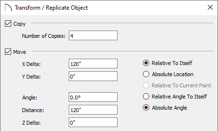
- Check the box beside Copy and specify the number of copies you would like to make. In this example, 4 copies are created.
- Check the box beside Move and specify the interval at which you would like the copied posts to be created. In this example, a Move interval of 120" along the X Delta is used.
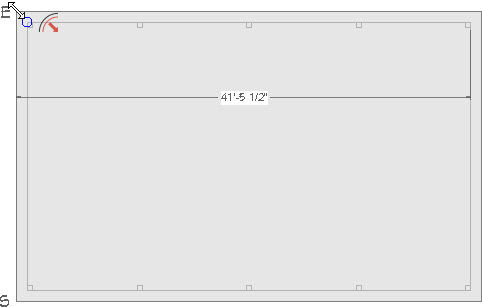
- Click OK to close the dialog and create the copies at the specified interval. In this example, a total of five posts spaced 10 feet (On Center) apart are produced.
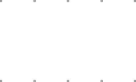
- Next, using the Select Objects
 tool, click and drag a rectangular marquee around all five posts to group-select them.

- With the five posts selected, click the Transform/Replicate Object edit button again. In the Transform/Replicate Object dialog:
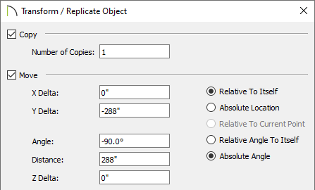
- Check the box beside Copy and specify 1 copy.
- Check the box beside Move and specify the interval to move the copied posts. In this example, the posts are moved 24 feet down on-screen, or -24' on the Y Delta then press your Tab key on your key board. You will see a value of -24' converts to -288".
- Click OK to close the dialog and create the copies at the specified interval.
- Open your program Preferences
 , and on the Behaviors panel, move the radio button to Concentric and set the Jump value, which is the distance you want between the outside of the posts and the edge of the structure's concrete slab, then click OK. In this example, 6" is used.
On a Windows PC, Preferences can be found by selecting Edit> Preferences from the menu and on a Mac selecting Chief Architect> Preferences from the menu.

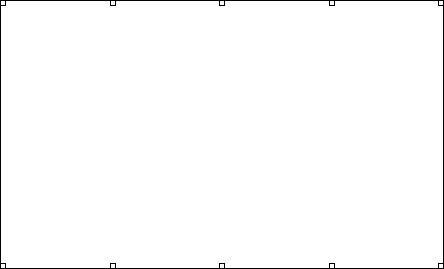
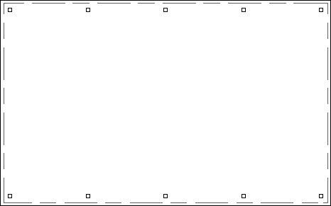
- Next, select CAD> Boxes> Rectangular Polyline
 from the menu, then click and drag a polyline that snaps to the outside of the array of posts.
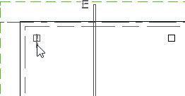
- Concentrically resize the polyline, so it represents the size of the slab you need by clicking on the polyline to select it, then Zoom
 in on a corner of the polyline. Since you've already set Concentric as the active Edit Behavior, slowly drag the corner outward until it snaps to one Jump increment of 6", then release the mouse button.
- Select Edit> Edit Behaviors> Default
 to return to the Default edit behavior.
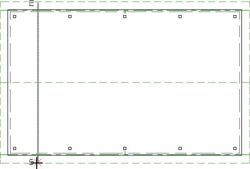
- Select Build> Wall> Room Divider
 from the menu, then draw Room Divider walls over the polyline that you created in the previous steps. When the Room Dividers completely surround the area they will automatically convert to full width, invisible walls.
- Using the Select Objects tool, click inside of the room's floor area to select the room, then click on the Open Object
 edit tool to display the Room Specification dialog.
- On the General panel, change the Room Type to Slab so there is no additional flooring on top of the slab foundation, then click OK.
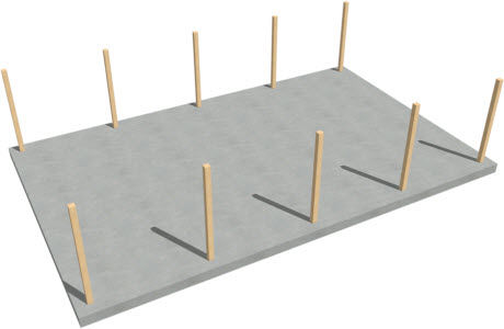
- Next, navigate to Build> Floor> Build Foundation
 from the menu. In the Build Foundation dialog, move the radio button under Foundation Type to Monolithic Slab and click OK.
- Finally, select 3D> Create Perspective Overview> Perspective Framing Overview
 from the menu to see the results so far.
To add the roof trusses
- Select File> Close View from the menu to close the framing overview and return to the floor plan view.
- From the currently active foundation level, go Up One Floor
 to Floor 1, select the two vertical side walls that were created using the Room Divider tool, then click on the Change to Gable Wall(s)
  edit tool on the Edit toolbar to change them to gable walls.
- Select Build> Roof> Build Roof
 from the menu. In the Build Roof dialog:
- On the Roof panel, check Trusses (no Birdsmouth).
- Specify the desired Pitch, Overhang, as well as any other settings, such as Materials.
- Check the box next to Build Roof Planes, then click OK to close the dialog and build a roof over the structure.
- Select Build> Framing> Roof Truss
 from the menu, then click and drag a line perpendicular to the roof ridge from one exterior wall to the opposite wall to draw a roof truss at that location.
If the "Framing, Roof Trusses" layer is not being displayed, then you may receive the following message: "The layer "Framing, Roof Trusses" is not displayed. Do you want to turn on the display of this layer in the current view?". Click Yes to this message to turn on the display of Roof Trusses in this view.
- To move the truss over the top of the first two posts on the left side of the building, select the truss and then click on the Center Object
 tool. Place your mouse over the top of one of the first posts until you see the vertical centerline indicator, then click.
- With the truss still selected, click the Transform/Replicate Object edit button. In the Transform/Replicate Object dialog:
- Specify the number of copies that you want across the building. In this example, 4 copies are specified.
- Set the distance between each truss by selecting the Move box and specifying a value in the X Delta. In this example, a value of 120" is used, which if you recall, is the same distance between each of the posts that we placed earlier.
- Click OK to close the dialog and create the copies at the specified interval.
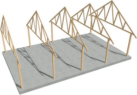
- Create a Perspective Framing Overview to see the results. Select File> Close View from the menu when you are finished to return to floor plan view.
To add the beams
-
Zoom in on the two posts located at the top, left, corner of the structure.
- Select Build> Framing> Floor/Ceiling Beam
 , then click and drag to draw a beam between these two posts. Drag the beam's end point to fall just short of the 2nd post.
If the "Framing, Ceiling Beams" layer is not turned on for display in this view, then you may receive the following message: "The layer "Framing, Ceiling Beams" is not displayed. Do you want to turn on the display of this layer in the current view?". Click Yes to this message to turn on the display of the Ceiling Beams in this view.
By default, beams will snap along their centerlines as they are drawn, and you can snap them to the post's midpoints.
- Go to the Window drop-down menu and select Fill Window Building Only
 .
.
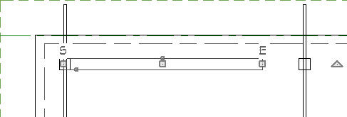
- Select the beam, then click and drag the end edit handle to the right. Cross over the top of all the posts and snap to the right side midpoint of the last post on the right side of the structure.
- To copy the beam to the line of posts on the opposite side of the building, select the beam, click on the Copy/Paste
 edit button on the edit toolbar, click on the Reflect About Object
  edit button on the edit toolbar, hover over the roof ridge line until you see the horizontal center line indicator, then click.
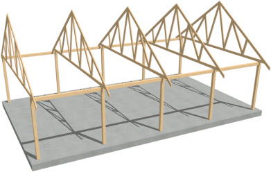
You should now have beams over each line of posts.
- Create a Perspective Framing Overview to see the results.
To add the purlins
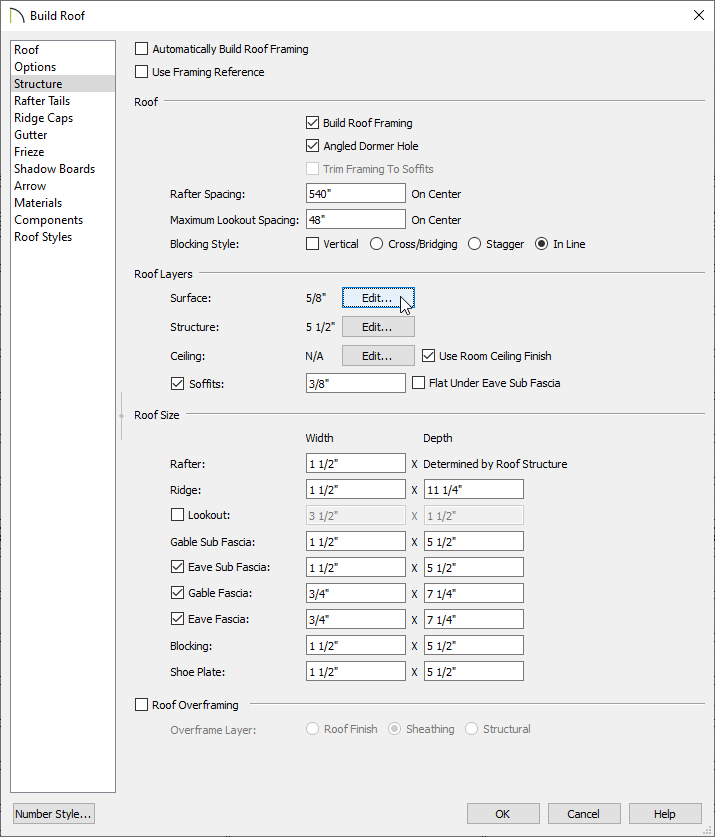
- Select Build> Roof> Build Roof from the menu.
- In the Build Roof dialog, on the Structure panel:
- Check the box for Build Roof Framing.
- Change the Rafter Spacing to be equal to, or greater than, the length of the building to prevent roof rafters from generating.
- Uncheck the box for Lookout.
- Click on Edit next to Surface under the Roof Layers section.
- In the Roof Surface Definition dialog:
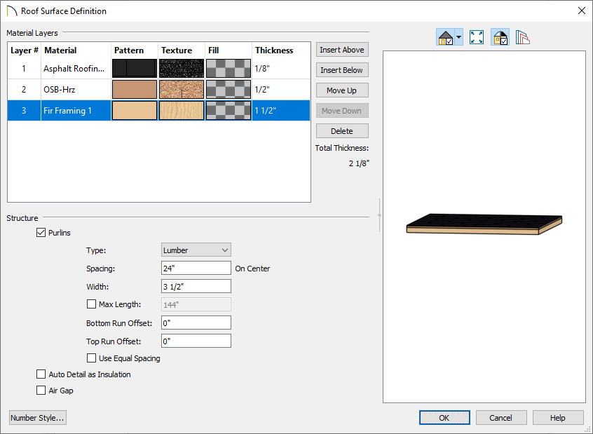
- Add a bottom layer with the framing material for the purlins and set the Thickness.
- With that new layer selected, check the Purlins box and then set the desired Type, Spacing, and Width.
- Check the box if you want to specify the Max Length of the purlins. This is available in X14 and newer program versions.
- Set the Bottom Run Offset and Top Run Offset.
- Check the box for Use Equal Spacing to space the purlins equally between the top and bottom runs.
- Click OK to close the dialog and OK again to build the purlins.