The information in this article applies to:

QUESTION
My project calls for a custom dentil molding. How can I create this in Chief Architect?

ANSWER
A custom dentil molding can easily be created in Chief Architect using 3D Solids or 3D Boxes, then converting them to a molding symbol using the Convert to Symbol tool.
To create a simple dentil molding
- Select File> New Plan
 to open a new, blank plan.
- Select Build> Primitive> 3D Solid
 , then click and drag to create a rectangular 3D Solid.
In X13 and prior versions, navigate to Build> Primitive> 3D Box instead.
- Click the Select Objects
 button, then click on the box to select it and click the Open Object
  edit button.
- On the 3D Solid/Box panel of the 3D Solid/Box Specification dialog that opens:
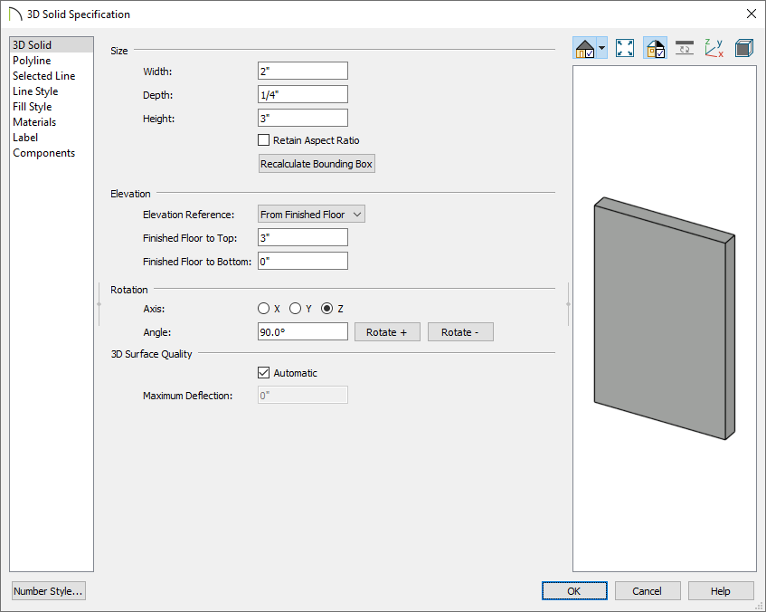
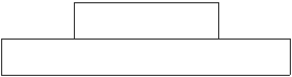
- Specify the Width, Depth, and the Height.
In this example we specified the Width as 2", the Depth as 1/4" and the Height as 3".
- Click OK to close the dialog and apply your changes.
- With the 3D Solid/Box still selected, click Copy/Paste
 , then Paste Hold Position
  .
.
-
Click the Open Object edit button.
-
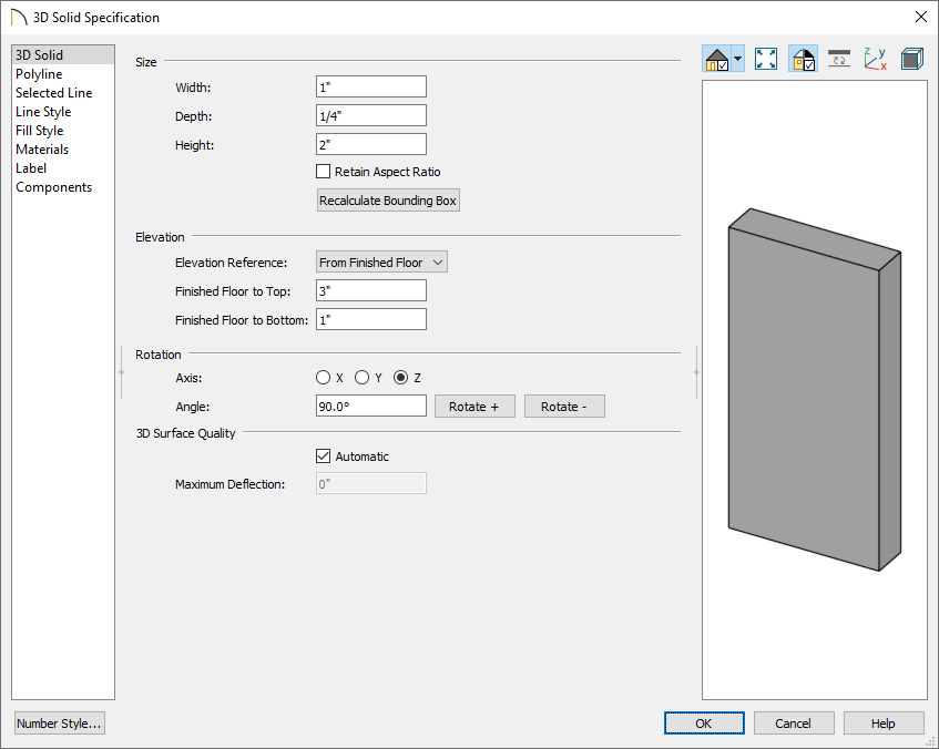
On the 3D Solid/Box panel of the 3D Solid/Box Specification dialog that opens:
-
Specify the Width, Depth, and the Height for this second 3D Solid/Box.
In this example we specified the Width as 1", the Depth as 1/4" and the Height as 2".
-
Click OK to close the dialog and apply your changes.
- With the smaller box still selected, click the Transform/Replicate Object
 edit button to display the dialog.
- In the Transform/Replicate Object dialog:
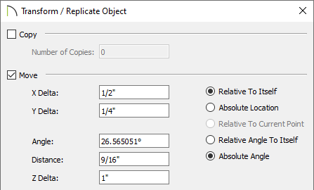
- Check the box beside Move.
- Specify the distance needed to move the small box on the X axis so that it is centered over the large box.
In this example, it is moved 1/2" in the X Delta, 1/4" in the Y Delta, and 1" in the Z Delta.
- Click OK to move the small box into position over the large box.
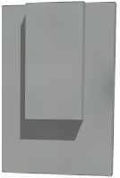
- Select 3D> Create Perspective View> Full Overview
 from the menu to see the results so far. .
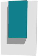
- The default material for 3D Solid/Box objects is concrete; however, you can apply any material you wish using the Material Painter. Select 3D> Material Painter> Material Painter
 from the menu.
- In the Select Material dialog, browse and select a material that appeals to you, then click OK.
- Click on each of the boxes to apply that material to them.
- If you wish, you can apply a different material to each box.
- When you are satisfied, select File> Close View to return to floor plan view.
To create a molding symbol
- With the Select Objects tool, drag a marquee over both 3D Solids/Boxes to select them.
You can also hold down the Control key on Windows or the Command key on Mac while clicking on both objects to select multiple objects.
- On the Edit toolbar, click on Convert Selected to Symbol
 .
.
- In the Convert to Symbol dialog:
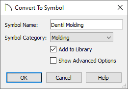
- Give the symbol a Name.
In this example, we used "Dentil Molding".
- Select Molding from the drop-down list of categories.
- Check Add to Library to save your molding symbol in the Library Browser under the User Catalog.
- Click OK to close the dialog.
- Your custom molding is now saved in the library.
The molding symbol is now ready to be used in any plan.
To apply symbol molding to a room
-
Open
 the plan in which you would like to use your custom dentil molding.
- Using the Select Objects tool, click inside of a room that you would like to apply the molding to, then click the Open Object edit button.
- On the Moldings panel of the Room Specification dialog that opens:
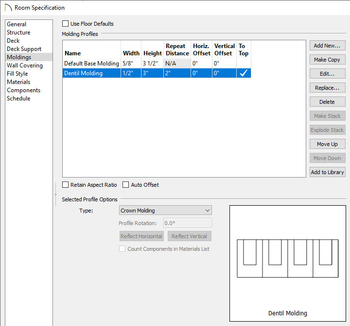
- Uncheck Use Floor Defaults.
- Click Add New to browse the Library Browser for your custom dentil molding, select it, then click OK.
- Modify the Width, Height, and Repeat Distance of the molding.
- Change the Horizontal and Vertical Offset values, as necessary.
By default the molding will be considered a Crown Molding and placed at the ceiling.
- Click OK once all desired changes have been made.
- Select 3D> Create Perspective View> Full Camera
 from the menu, then click and drag a camera inside of the room to see the results.