The information in this article applies to:

QUESTION
I would like to show the location and routing of gas lines, HVAC runs, as well as hot water and cold water plumbing lines in my floor plan. How can I do this?

ANSWER
You can use custom layers along with specific line styles to draw gas, HVAC, and plumbing lines in your plans.
To learn how to generate 3D ductwork, as well as how to locate and place 3D HVAC and Plumbing symbols, please see the Related Articles section below.
To create new layers
- Switch to the Plan View that will be used to focus on HVAC and plumbing schematics.
In this example, we will switch to the Mechanical Plan View, which is part of the default plan template in X14. If you're using an X13 or prior template, this was called the HVAC Plan View. Feel free to also create your own Plan View if you wish.

- Select Tools> Layer Settings> Display Options
 from the menu.
-
In the
Layer Display Options dialog that opens:

-
Under the Properties for Selected Layer section, click on the Color box and select the color you would like to use for the lines of this layer.
- Next, use the Line Style drop-down to select an appropriate line style from the list or click on the Library button to browse the Library for your desired line style.
In this article, all of the line styles that are used are located in the Library by navigating to Chief Architect Core Catalogs> Line Styles.
- Repeat steps 2-4 for any remaining layers you would like.
In this example, we have created and defined a total of 4 new layers:
- Gas Lines
- Plumbing Cold Water
- Plumbing Hot Water
- Plumbing Waste Water

- Click OK once the layers have been defined to your liking.
To draw gas, HVAC, and plumbing lines
- Navigate to CAD> Current CAD Layer
 from the menu.
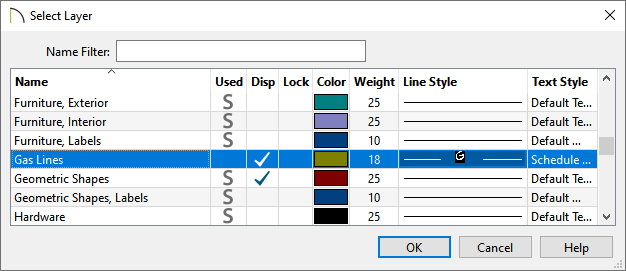
- In the Select Layer dialog that opens, select a gas, HVAC, or plumbing layer, then click OK.
- Now, objects that are drawn using Lines
 , Arcs
  , Circles
  , Boxes
  , Spline
  , and other various CAD tools will be placed onto the selected layer and will display the color and line style set for that layer.
- After all of the objects that you'd like to be on that layer are created, change the Current CAD Layer to another layer of your choice, then repeat Step 3. Perform this procedure until all of the gas, HVAC, and plumbing lines are to your liking.
