The information in this article applies to:

QUESTION
It is sometimes necessary to cut an existing floor joist to make room for a crawl space access point or to provide room for a toilet's drain pipe.

ANSWER
Framing can be modified after creation to allow for unique situations, like providing room for a drain pipe in an as-built plan. A polyline can be used to cut the framing members and then additional support can be added with the General Framing Member tool.
To create a hole in existing framing
- Go to the floor where the framing you want to modify is located.
The floor framing for a given floor is always created on the floor below. For example, to modify the floor joists of Floor 1 you'll need to go to Floor 0.
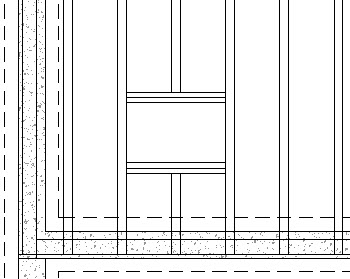
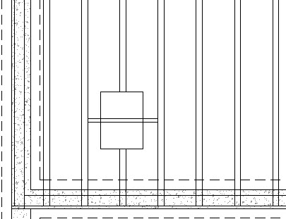
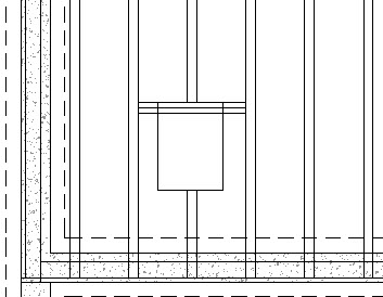
- From the menu select CAD> Boxes> Rectangular Polyline
 then click and drag a box about the size of the hole necessary, overlapping the framing members that need to be cut.
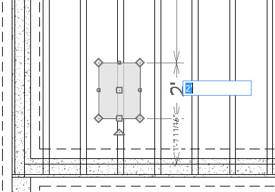
- Use Temporary Dimensions to specify the exact size of the rectangular polyline.
If you need to see where a fixture is located on the above floor then the Reference Floor Display can be used. To learn more, see KB-00475 on Turning on the Reference Display.
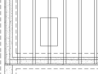
- With the rectangular polyline selected, click on the Trim Objects
 edit tool on the Edit Toolbar, then click and drag a line over the framing member section you want to remove in order to delete it.
To add supplemental framing members
- Select Build> Framing> General Framing
 then click and drag a framing member across the hole.
- With the Select Object
 tool, select that framing member and then click Open Object
  to open the Framing Specification.
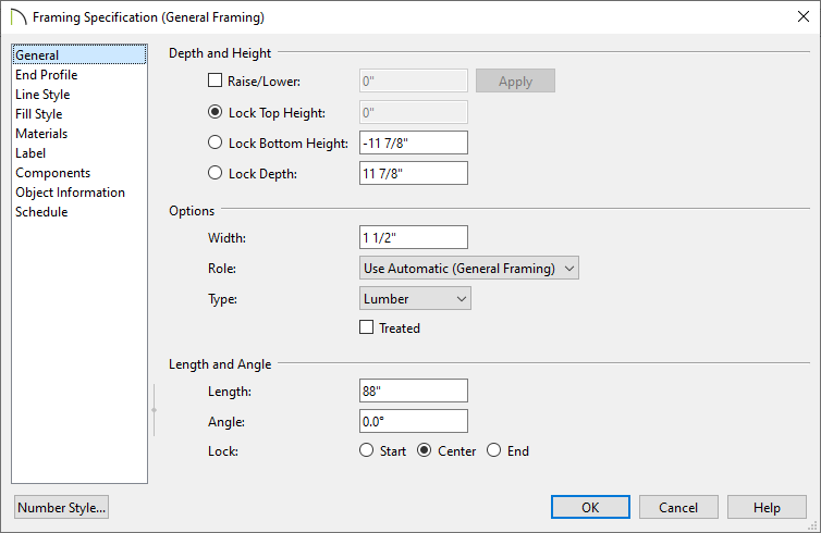
- In the Framing Specification, on the General panel, specify the Depth of the framing member.
![]()
For this example, the depth is set to 11 7/8" to match the floor joists.
![]()
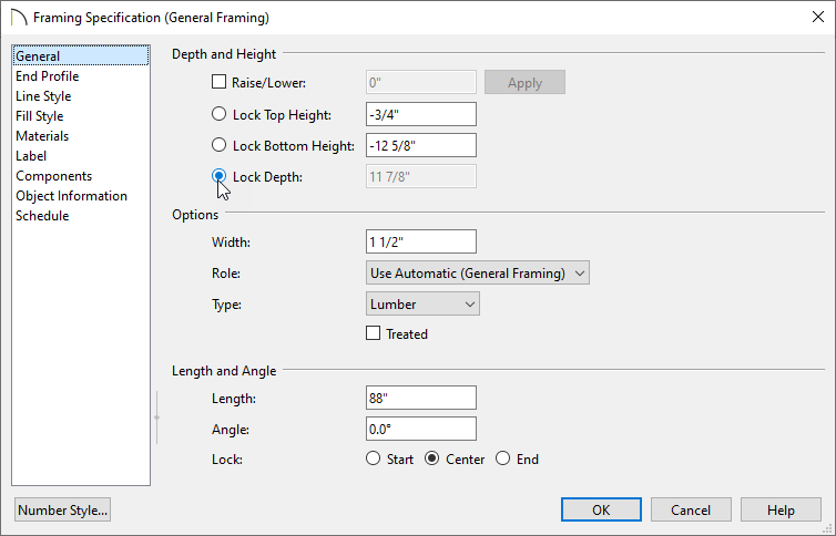
- Once the Depth is specified, lock the Depth by selecting the radio button, and then set the Top Height to -3/4" so that the framing member generates under the floor sheathing.
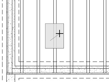
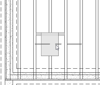
- With the Select Objects tool, select the framing member and move it into place at the side of the hole.
- With the framing member selected, click Copy/Paste
 edit button, and click in the hole to place a second framing member.
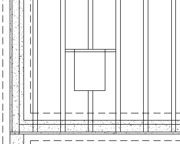
Select it and move it beside the first, as shown in the image below.
- Group select the two framing members by holding down the Shift key on the keyboard, and then clicking on each framing member.
- Once the two framing members are selected, click the Copy/Paste tool and then click the Reflect About Object
 tool.
tool.
Move the cursor into the drawing space and orient the reflection line across the middle of the rectangular polyline hole and click.
- With the Select Objects tool select the polyline rectangle and Delete
 it.
it.