QUESTION
When I insert a sink into a cabinet, the countertop hole doesn't look correct. How can I customize this cutout to my liking?

ANSWER
When a sink fixture is placed into a cabinet, a hole will typically be cut out of the countertop automatically. In some instances though, such as when you're using a third party sink symbol that was imported, this cutout may not generate as you would expect.
If this occurs, you can adjust the CAD block associated with a sink fixture so that the cutout better suits your needs.
To customize a sink's cutout
- In a New Plan
 , locate and select the sink fixture that you would like to create a custom sink hole for from the Library Browser
  , then place it an empty area of the plan.
A Question dialog may appear stating that "The symbol you are trying to place was designed to be placed onto the top of a base cabinet but you did not select an appropriate cabinet. Would you like to place the symbol as a free standing object?" Click Yes.
- Navigate to CAD> CAD Block Management
 from the menu.
- In the CAD Block Management dialog that opens, locate the custom sink, select it, then click Insert.
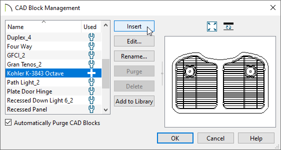
- Click in an empty area of the plan to place the CAD block.
- Using the Select Objects
 tool, click on the newly placed CAD block to select it, then click the Explode CAD Block
  edit tool.
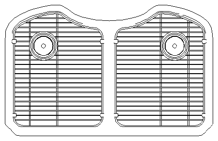
- With the block exploded, select the outermost polyline that pertains to the sink, then click the Convert Polyline
 edit tool.
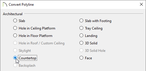
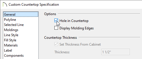
- The Convert Polyline dialog will appear. Select the Countertop option and click OK.
- The Custom Countertop dialog will then appear. Check the Hole in Countertop box and click OK.
- Group select all of the CAD components and select the Make CAD Block
 edit tool to block all of the CAD components back together.
This is a good time to open the newly formed CAD block up to specification and provide an appropriate name. If a name is not specified for the block, it will simply be titled "block".
- Locate the sink fixture within the Library Browser once again, right-click on it, and choose Open Object
 .
.
In X14 and prior versions, select Open Symbol  from the contextual menu instead.
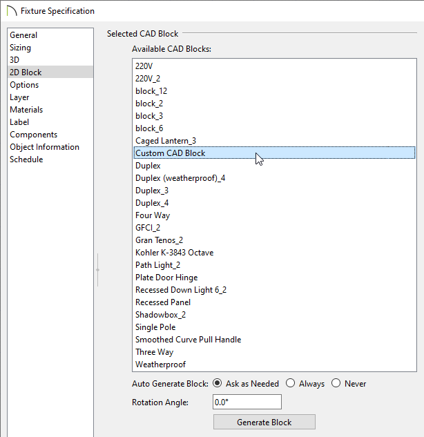
- On the 2D Block panel of the Specification dialog that opens, select the CAD block that was customized in the steps above, then click OK.
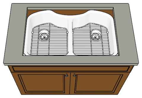
You can now insert the sink fixture from the Library Browser into a cabinet, and the cabinet's countertop will conform around the sink.