QUESTION
I am working on an addition for a remodel project, is there a way that I can show the walls for the as-built structure compared to the new proposed walls in the same plan?
ANSWER
A great way to show the as-built condition on a remodel project is to create an "As-Built Mask" using a CAD block of the existing structure.
To have the CAD block only contain the necessary items, turn off the layers of any items unnecessary to the remodel. For example, furniture, cabinets, window labels, and roof planes. Also, a new layer needs to be created for the as-built mask.
If you would like to learn more about using Chief Architect for remodeling, please see the
Remodeling Video Playlist which details the CAD mask process discussed below, as well as the option to reference other plan files starting with X11.
To setup your layers
- Select Tools> Layer Settings> Display Options
 from the menu.
- In the Layer Display Options dialog, use the Layer Sets drop-down at the top to choose the All Layers OFF layer set.
- Click Copy Set to make a copy of this layer set.
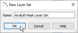
- In the New Layer Set dialog, specify a Name for this layer set, then click OK. In this example we used As-Built Mask Layer Set.
- Make sure the As-Built Mask Layer Set is now selected and then turn on any layers that you want to see in the As-Built Mask.
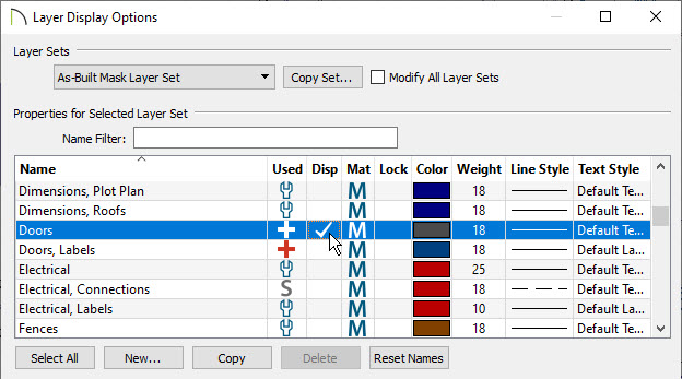
In our example, we enabled the following layers:
-
Doors
-
Stairs & Ramps
-
Walls, Normal
-
Walls, Main Layer Only
-
Windows
- Once you have turned on the layers you need, click the New button and create a new layer named CAD, As-Built Mask, then click OK.
- Click OK to close the Layer Display Options dialog.
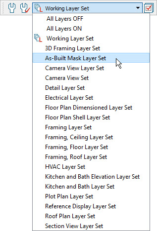
- In a floor plan view, switch the layer set to the As-Built Mask Layer Set by using the drop-down menu on your toolbar.The layer set can also be switched if it's linked to a Saved Plan View.
To learn more about Saved Plan Views, please see the following
Training Videos.
To make a CAD Detail
- Center the plan on screen by selecting Window> Fill Window Building Only
 .
.
- Click CAD> CAD Detail From View
 from the menu to create a new CAD detail.
- Click CAD> CAD Detail Management
 from the menu to open the CAD Detail Management dialog.
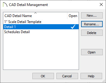
Here we can see the new CAD detail has been named Detail 1 but if there are other details in your plan, you may want to rename it:
- Highlight the new detail, click the Rename button, and rename it to As-Built Mask and click OK.
- Click OK on the CAD Detail Management dialog to accept your changes and close it.
To adjust the line styles
- With the Select Objects
 tool, click and drag a selection marquee around the CAD detail.
Alternatively, you can navigate to Edit> Select All from the menu to select all CAD components present in the CAD detail.
- Click the Open Object
 edit tool to open the Object Specification dialog.
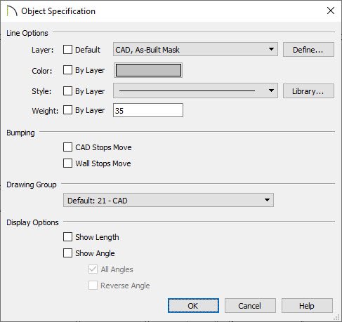
In this example we are adjusting the Line Options to the following:
-
Layer: CAD, As-Built Mask
-
Color: Gray
-
Style: Solid Line
-
Weight: 35
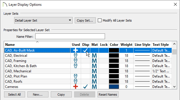
- Click the Define button next the Layer option shown above to open the Layer Display Options dialog, and place a check in the Disp column for the CAD, As Built Mask layer.
- Click OK and OK again to apply these changes and close the dialogs.
To convert our mask into a CAD block
- With the Select Objects tool, click and drag a selection marquee around the whole detail.
- On the edit toolbar, click Make CAD Block
 .
.
- Select Open Object to display the CAD Block Specification dialog.
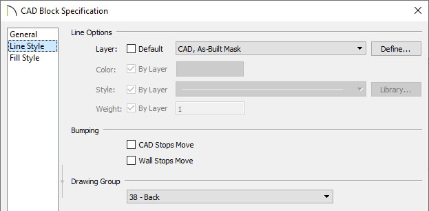
- On the General panel, assign a Block Name of As-Built Mask.
- On the Line Style panel, change the Layer to the CAD, As-Built Mask layer.
- Under the Drawing Group, select Back.
- Click OK to accept your changes.
To place the CAD block
- Using the Select Objects tool, select the CAD block and then select Edit> Copy
 from the menu.
- Switch back to the floor plan view.
- Select Edit> Paste> Paste Hold Position
 from the menu to paste the CAD block under your existing plan.
- Use the Active Layer Set drop-down menu again to switch back to the Working Layer Set, or whichever layer set you prefer to work in.
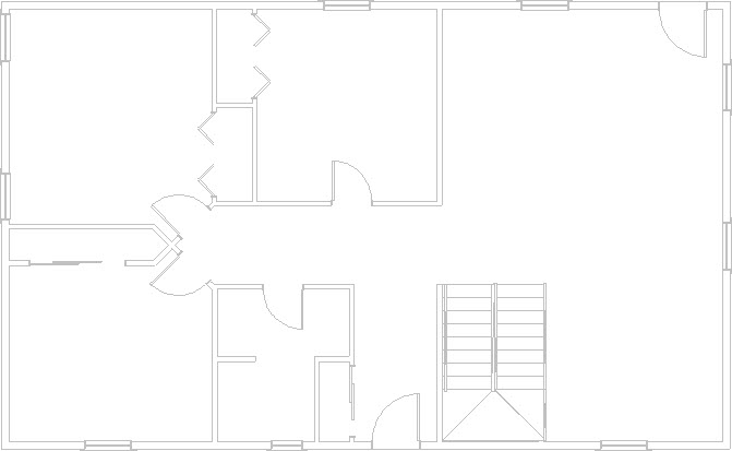
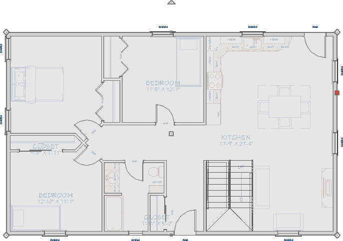
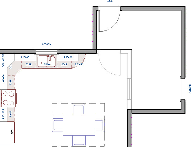
- When walls are moved, the CAD block representing the As-Built Mask will display in the background.
You can lock the CAD, As-Built Mask layer which will make the mask unselectable. This makes it easier to work with the plan as the mask can no longer get in the way.