QUESTION
How can I create a bell footing?
ANSWER
As the name implies, a bell footing is a bell-shaped footing at the base of a pier. While there is not an automatic bell footing tool in Chief Architect, creating one manually is a straight-forward task using objects from the Geometric Shapes library category.
In this example, a bell footing is created from the bottom up by stacking cylinders and pedestal objects. We will also learn how to place the footing under a foundation pier as well as how to add this footing to the Library Browser for use in any plan.
To place and modify a cylinder
-
Open
 the Chief Architect plan in which you would like to create a bell footing.
- Select Tools> Reference Floors> Down One Floor
 to go to the Foundation floor
- If you do not have a foundation, select Build> Floor> Build Foundation
 from the menu.
- In the Foundation Defaults dialog, specify a Grade Beams on Piers foundation, then click OK.
- If the Library Browser side window is not already open, navigate to View> Library Browser
 .
.
- Navigate to Chief Architect Core Catalogs> Shapes> Cylinders, and select the Vertical Cylinder (large).
You can also use the Cylinder tool for this process, which can be accessed by navigating to Build> Primitive> Cylinder.
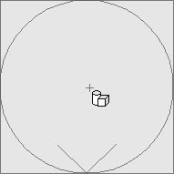
- When you move your cursor into the drawing area, it will display the Geometric Shapes
 icon. Click once in an empty space near your foundation to place a cylinder at that location.
- Using the Select Objects
 tool, click on the cylinder to select it, then click the Open Object
  edit button.
- On the General panel of the Geometric Shape Specification dialog that displays:
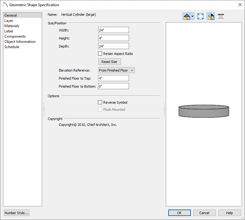
- Specify the Height of the bottom section of the footing.
- Specify the Width and Depth of this bottom section.
- On the Materials panel, select the Cylinder component, click the Select Material button, then browse the library for an appropriate concrete material. Once a material has been chosen, click OK.
- Once all desired changes have been made to the base of the footing, click OK again.
To create the bell footing
- In the Library Browser, browse to Chief Architect Core Catalogs> Shapes> Pedestals, select the Cylindrical pedestal, then click once in a floor plan view near the cylinder created in the section above.
- Using the Select Objects tool, click on the pedestal to select it, then click the Open Object edit button.
- On the General panel of the Geometric Shape Specification dialog that displays:
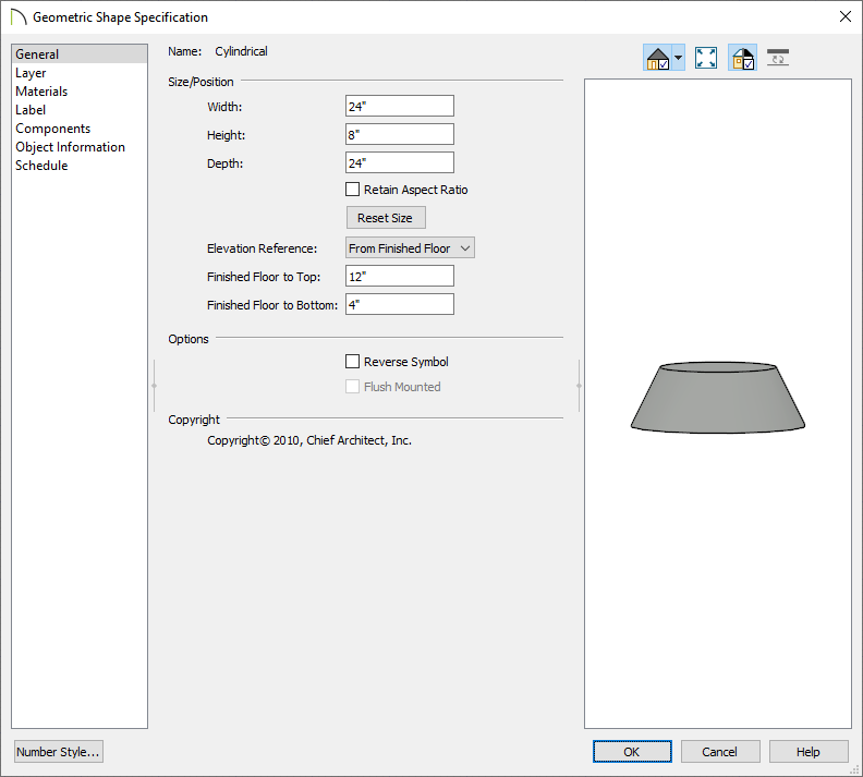
- Specify the Height of the next section of the footing.
- Specify the Width and Depth.
- Specify the Floor to Bottom height. This will be the same as the Height of the cylinder below it.
- On the Materials panel, select the Cylinder component, click the Select Material button, then browse the library for an appropriate concrete material. Once a material has been chosen, click OK.
- Once all desired changes have been made to the cylindrical pedestal, click OK again.
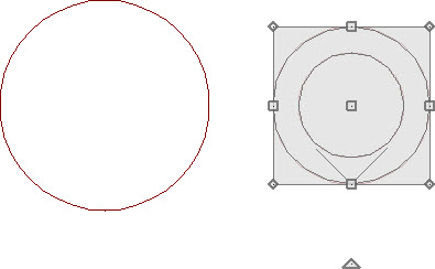
- With the pedestal still selected, use the Move
 edit handle to move it into position directly over the cylinder.
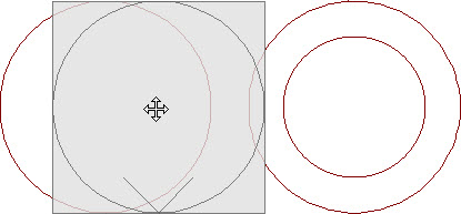
- Hold down the Ctrl/Command key on your keyboard to override move restrictions.
- Using the Point to Point Move
 edit tool can help you snap the center of pedestal to the center of the cylinder base. For more information on this tool, please see the Related Articles section below.
- To see the results so far, select 3D> Create Orthographic View> Backclipped Cross Section
 , then click and drag a camera arrow through the two geometric shapes.
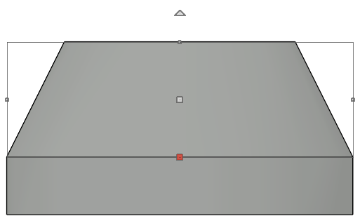
In the image above, the pedestal is selected to distinguish between the two shapes.
- Select File> Close View to close the cross section view and return to floor plan.
- If you need to make the bell footing taller and narrower at the top after placing one pedestal, you can repeat these steps to place a second pedestal on top of the first.
To place the footing under a pier
- Using the Select Objects tool, click and drag a rectangular selection marquee around the stacked geometric shapes to select them.
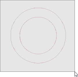
- With the objects selected, click on the Make Architectural Block
 edit button to group the shapes into a single object.
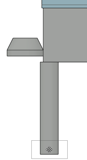
- Select 3D> Create Orthographic View> Backclipped Cross Section , then click and drag a camera arrow through the footing, and at least one pier.
- In the cross section/elevation view, select Window> Zoom
 from the menu, then click and drag a rectangular zoom marquee around a pier and footing.
- Click on the architectural block to select it, then use the Move edit handle to move it so that it's centered under the pier and at the proper height, as being demonstrated in the image below.
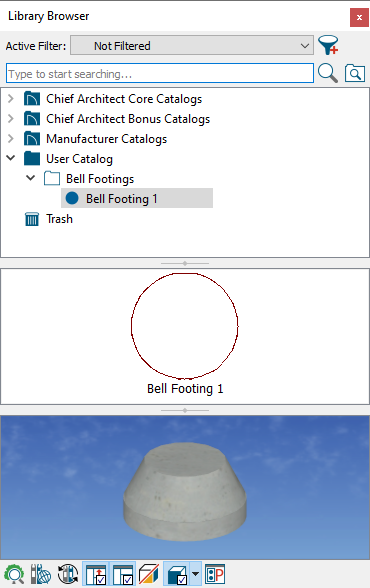
To add the footing to your library
- Using the Select Objects tool, click on the architectural block that represents the footing, then click the Add to Library
 edit button to add the block to the Library Browser.
- You can then choose to Rename this object, and move it to the appropriate folder that you have created for it.