The information in this article applies to:

QUESTION
I am working on a Dutch Colonial gambrel roof and need to add flared eaves. What is the best way to do this?

ANSWER
You can easily join two roof planes using the Join Roof Planes edit tool. The program takes the current positions and heights of the two roof planes, finds the line along which the two planes can join, and then extends or contracts their edges as required to do so.
When manually adding eaves to a roof, though, you typically need the roof planes to join at a specific height and/or along a particular line. You can achieve this in a few simple steps.
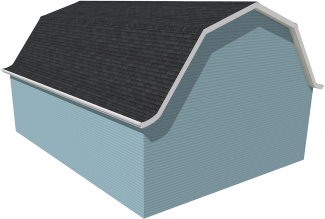
In this example, we will add flared eaves, sometimes referred to as a Dutch kick, to an automatically generated gambrel roof. This will require three different roof planes on each side of the ridge.
To create an automatic gambrel roof
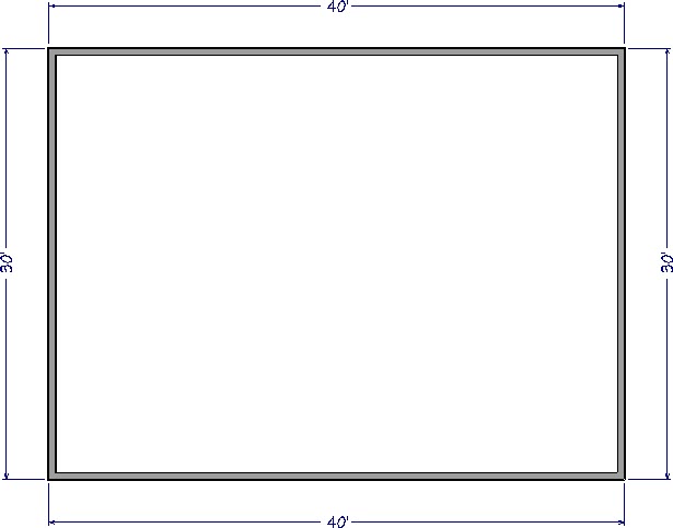
- Create a New Plan
 and draw four walls to form a rectangle.
In this example, a 30' by 40' structure is created.
- Select Build> Roof> Build Roof
 from the menu, and on the Roof panel of the Build Roof dialog that displays:
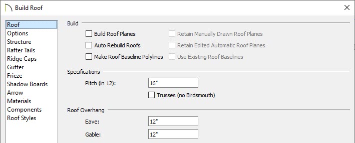
- Specify the Pitch (in 12) of the steep lower roofs of the gambrel.
In this example a, a Pitch of 16" in 12" is specified.
- Specify the desired depth of the Roof Overhangs.
In this example, both Eave and Gable Overhangs are set to 12".
- Do not check Build Roof Planes as we aren't quite ready to build the roof yet.
- Click OK to confirm the changes and close the dialog.
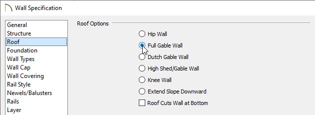
- Using the Select Objects
 tool, click on one of the vertical walls in the plan, hold down the Shift key on your keyboard, then click on the other vertical wall to select them both at the same time.
- With the two walls selected, click the Open Object
 edit button, and on the Roof panel of the Wall Specification dialog that displays, select the Full Gable Wall option, then click OK.
- Next, select the two horizontal walls, click the Open Object edit button, and on the Roof panel of the Wall Specification dialog that displays:
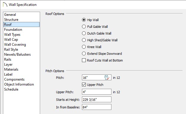
- Check the box beside Upper Pitch.
- Specify the desired Upper Pitch value.
In this example, 4" in 12" is used.
- Specify either the Starts at Height, which is the height above the floor that the second pitch begins, or the In from Baseline value, which is the distance in from the outside of the wall framing that the second pitch begins.
In this example, an In from Baseline value of 84" is specified.
- Click OK to confirm the changes and close the dialog.
- Select Build> Roof> Build Roof from the menu and in the Build Roof dialog, check the box beside Build Roof Planes, then click OK.
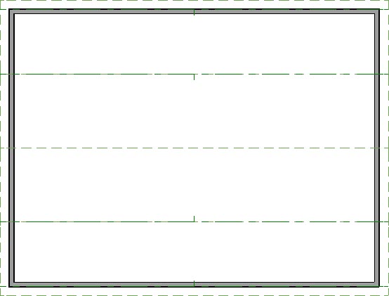
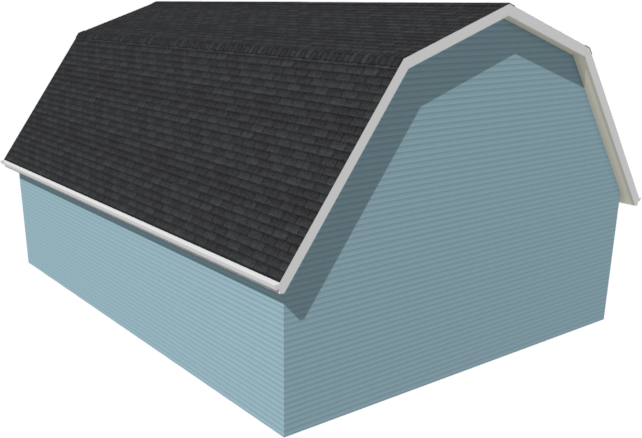
- Select 3D> Create Perspective View> Perspective Full Overview
 from the menu to see the results so far.
To add curved or flared eaves
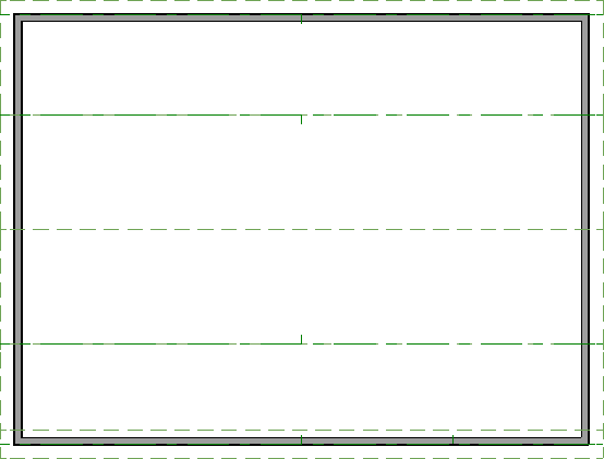
- In a floor plan view, use the Select Objects tool, and click on one of the lower roof planes' eave edges to select it.
In order to accommodate a curved roof plane for the eave, this roof plane edge needs to be pulled back.
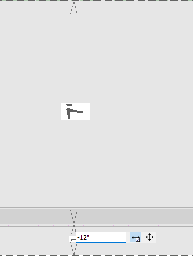
- Click on the temporary dimension line that displays the 1' overhang value.
If you do not see a dimension line when the roof plane is selected, click View> Temporary Dimensions to turn on the display if temporary dimensions. If there are dimensions already annotating the measurements of the area, temporary dimensions will not display.
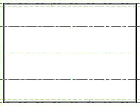
- In the inline text field, type the distance the eave edge should be moved to, then select the Enter key on your keyboard. To move the selected edge from the outside of the wall to the inside, use a negative number.
In this example, a value of -12" is specified, which adjusts the edge of the roof plane a total of 24" (2') from its original location.
- Select Build> Roof> Roof Plane
 from the menu, then click and drag to draw a roof plane that bears on one of the horizontal walls. This roof plane will become a curved eave, or Dutch kick.
- Click and drag to draw the baseline along the outside of the wall's framing layer.
- Release the mouse button and move your cursor in the direction of the roof's ridge.
- As you move the mouse, a preview outline of the roof displays and will snap to the eave edge of the roof plane that you re-positioned.
- Click once to set the location of the ridge edge and finish creating the roof plane.
- With the new roof plane still selected, use its edit handles to extend it across the width of the structure, to match the upper roof planes.
- Once the width has been adjusted, click the Open Object edit button.
- On the General panel of the Roof Plane Specification dialog:
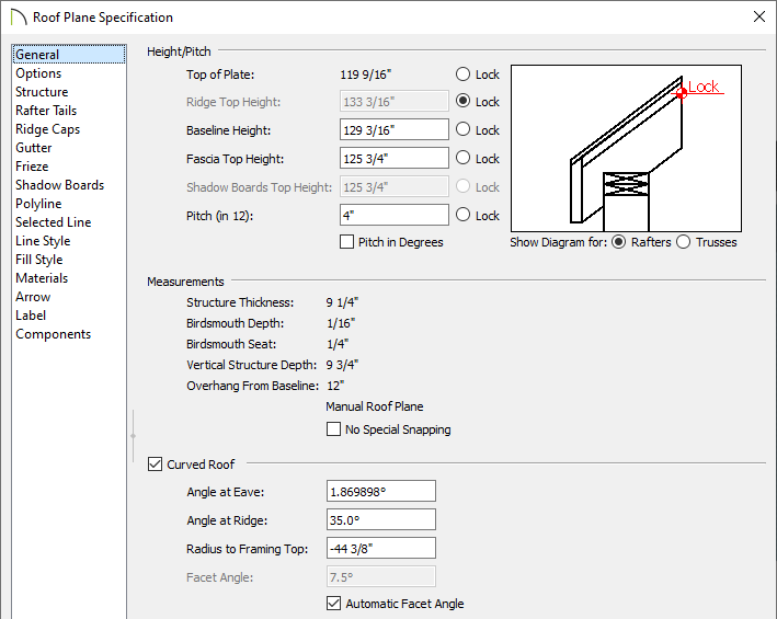
- Click the radio button next to Ridge Top Height to lock it, and then enter the desired Pitch (in 12) for the part of the roof that is furthest from the ridge.
In this example, the Pitch is set to 4" in 12".
- Check the box beside Curved Roof and specify an Angle at Eave, Angle at Ridge, or Radius to Framing value.
In this example, an Angle at Ridge value of 35.0° degrees is set.
For more information on each of these fields, click on the Help button at the bottom of the Roof Plane Specification dialog box.
- Click OK to confirm the changes and close the dialog.
- Repeat steps 1-5 on the opposite end of the structure.
- Finally, create a Perspective Full Overview to see the results.