QUESTION
Can I limit what I see with a cross section or elevation camera?
ANSWER
In Chief Architect, cross section/elevation camera views can be clipped in various directions, allowing you to cut or remove the display of objects from the view, including entire floors. This is a great way to isolate a single room, a single floor level, or a specific area in the plan.
The ability to step a cutting plane is also helpful if you want to cut objects from the view, even if they're located on the same floor level.
To clip a cross section/elevation view using the specification dialog
- Navigate to 3D> Create Orthographic View, then select the Cross Section/Elevation
 , Backclipped Cross Section
  , or Wall Elevation
  tool.
tool.
Automatic elevation views can also be created. To create exterior elevations that will display content from all floors, navigate to 3D> Create Auto Elevations, then choose an appropriate option. To create interior elevations that will display content from a specific room on a specific floor level, select a room, then click on the Create Room Elevation Views edit tool.
- With the tool selected, click and drag towards a wall to create a section/elevation view.
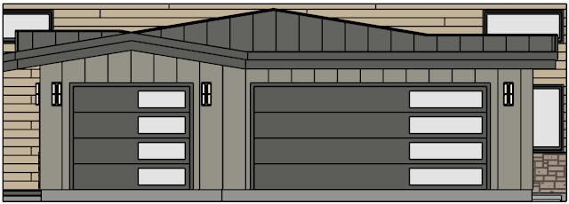
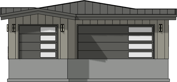
In this example, the Cross Section/Elevation tool was used to create an exterior elevation, as shown in the image below.
- In the section/elevation view that generates, navigate to Tools> Active View> Edit Active View
 .
.
In Home Designer Pro, navigate to 3D> Edit Active Camera  instead.
- On the Camera panel of the Specification dialog that displays, focus on the settings located under the Scene Clipping section.
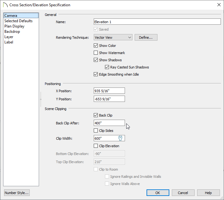
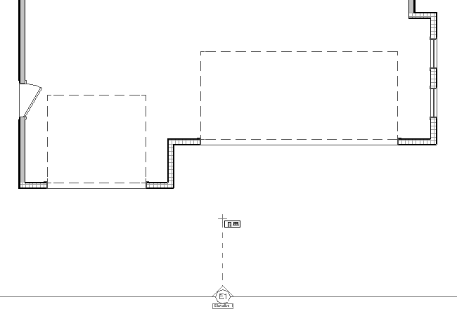
- If you want to control how far back the view captures, you can place a check in the Back Clip or Back Clip After box, then specify a distance between the view's initial cross section line and a backclip line. This will allow you to see objects or portions of objects located between the start and end lines shown in a plan view. This box is checked by default for Backclipped Cross Section views.
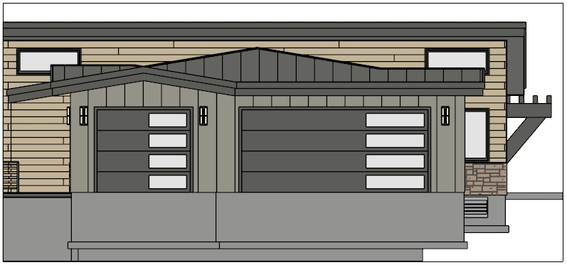
In this example, we have checked the Back Clip box and specified a Back Clip After value of 400".
- Check Clip Sides or Clip To Sides to limit the selected view’s side-to-side extents. When checked, edit handles will display at each end of the cross section line in a plan view, allowing you to drag them to adjust the view.
In X13 and Home Designer Pro 2022, you can also specify a Clip Width value.
- In X13 and Home Designer Pro 2022, the ability to clip the top and/or bottom of the view was implemented. Check the Clip Elevation box, then specify values for the Bottom Clip and Top Clip Elevation fields.
In X12, Home Designer Pro 2021, and prior versions, use the Wall Elevation tool to limit the content displayed to a specific floor level. Note that when using this tool in prior versions, the elevation view will only display content for the room the view was created in.
The display of the foundation floor level can also be controlled using layers. To learn more, please see the "Turning Off the Display of the Foundation in a Cross Section/Elevation View" resource located in the Related Articles section.
- Also in X13 and Home Designer Pro 2022, a Clip to Room setting is available. When checked, the extents of the current view will be confined to the room that the camera is located in. The view's clip values are reported above for reference, but will be grayed out. This box is checked by default for Wall Elevation views and is only available if the camera is located inside of a room.
This setting is the equivalent of using the Wall Elevation tool in X12, Home Designer Pro 2021, and prior versions.
When this setting is checked or a Wall Elevation camera is being edited, some additional options are available:
-
Ignore Railings and Invisible Walls will ignore the room definition created by these types of walls.
- In X13 and Home Designer 2022, Ignore Walls Above will prevent any walls located above the selected camera's room from displaying in the view. This option typically has an effect only when the camera's room has Flat Ceiling Over This Room unchecked, or the room above has Floor Under This Room unchecked, in the Room Specification dialog.
-
Once all desired changes have been made, click
OK.
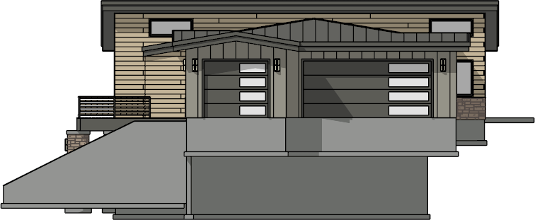
Specifying a backclip line with an appropriate distance value allowed us to isolate the garage, as shown in the image below. If we wanted to remove the foundation from the view, we could have also checked the Clip Elevation box and raised the value of the Bottom Clip Elevation using X13 or Home Designer Pro 2022.
In X13 and Home Designer Pro 2022, clipping plane lines were introduced. If you don't want to see the clipping lines in a section or elevation view, access the Layer Display Options or Active Layer Display Options side window, locate the "CAD, Clip Lines" layer, then remove the check from either the Disp column or the Display checkbox.
To clip a cross section/elevation view using clipping plane lines*
*Applies to Chief Architect X13, Home Designer Pro 2022, and newer versions.
- In a cross section/elevation view, navigate to Tools> Active View> Edit Active View .
In Home Designer Pro, navigate to 3D> Edit Active Camera instead.
- On the Camera panel of the Specification dialog that displays, check the Clip Sides and/or Clip Elevation box, then click OK.
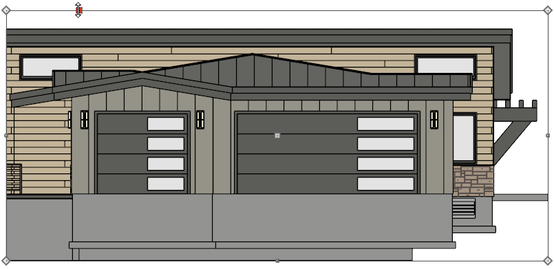
- In the cross section/elevation, clip lines will be appear on the sides if Clip Sides was checked in the step above, or on the top and bottom if Clip Elevation was checked.
- Using the Select Objects
 tool, select a clip line and use the various edit handles that display to adjust its position.
- If you don't want one of the clip lines to be a straight line/edge, you can use the various edit buttons that display on the Edit toolbar to modify the shape:
- Use the Add Break
 tool to add a break point on a clip line.
- Use the Change Line/Arc
 edit button to change a line to an arc.
- Repeat steps 4-5 with the other clip lines until the view is clipped, or cropped, to your liking.