The information in this article applies to:

QUESTION
On many occasions I have used Chief Architect to construct a single building. However, now I would like to create a subdivision. What approach do you recommend?

ANSWER
Not only is it possible to design a subdivision neighborhood, or lot with multiple structures in it with Chief Architect, it is also relatively easy. While Chief Architect is designed to create a single home in a single drawing, there is no set limit to the number of homes that may be included in any one drawing. In the past, customers have completed similar projects - including an international airport and large city park - using Chief Architect.
When designing such large projects, however, it is important to keep in mind that Chief Architect was designed to draw one building within a single drawing. Recommendations to customers who want to use Chief Architect to design a subdivision or a small town include:
-
Model each single family home in it's own plan file. Eventually, each customer you work with will require customization and changes to their particular home. Also, you will need to print their plans to obtain permits. Both of these tasks are made easier if you only have one house in a drawing.
-
The subdivision itself should be in a separate drawing in which you model the terrain, streets and sidewalks, and other features of the development.
-
Export each house plan out of Chief Architect as a 3D symbol and then import each as a symbol in the subdivision drawing. Within the subdivision drawing, home symbols can be positioned as needed.
To convert a plan to a 3D symbol
-
Open
 the Chief Architect plan that you would like to convert into a 3D symbol.
- Select Tools> Layer Settings> Display Options
 from the menu and click the Copy Set button at the top of the dialog.
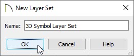
- In the New Layer Set dialog, type a short, descriptive name for this layer set, such as 3D Symbol Set, then click OK.
- Scroll down the list of layers and ensure that the items you want to have displayed, such as walls, doors, and windows, have a checkmark in the Display checkbox or a checkmark in the Disp column.
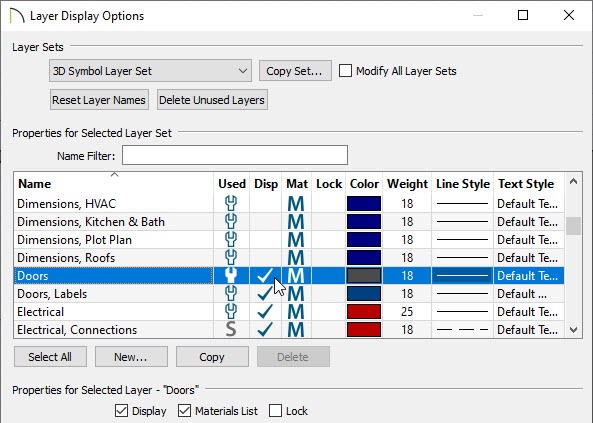
- Then, uncheck the display of any layers that do not affect the appearance of the plan's exterior, such as "Furnishings, Interior" and "Fixtures, Interior." This will help minimize the number of surfaces your symbol will have and improve rendering time for the subdivision.
- Be sure to turn off the display of all terrain layers.
- When you are satisfied with the settings in your new layer set, click OK to close the dialog and apply your changes.
- Select 3D> Create Perspective View> Perspective Full Overview
 from the menu, and then make sure the newly created layer set is being used.
- In the overview of the plan, select Tools> Symbol> Convert to Symbol
 from the menu.
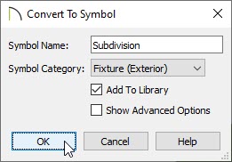
- In the Convert to Symbol dialog, provide an appropriate name for the symbol that's being created.
- Using the Symbol Category drop-down, select "Fixture (Exterior)."
- Make sure Add To Library is checked.
- Click OK and the 3D model will be saved in your User Catalog.
-
Once converted and added to the library, the symbol can be placed in any plan. It can be selected, moved and rotated as needed using its edit handles, and its materials can be altered using the
Material Painter 
. You can also control its height on the
General panel of the
Fixture Specification dialog.
-
To see the results, select
3D> Create Perspective View> Perspective Full Overview from the menu.