The information in this article applies to:

QUESTION
How do I create a fireplace mantel in Chief Architect?

ANSWER
A mantel can be created in Chief Architect using millwork objects found in the Library Browser. Moldings can then be added to the to the mantel, if desired.
Creating a mantel using millwork library objects
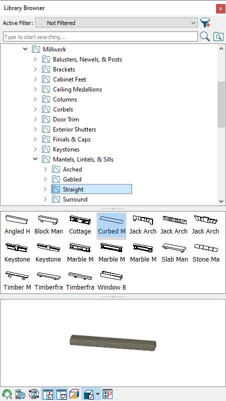
- If the Library Browser is not already open, navigate to View> Library Browser
 .
.
- Select and place any objects you'd like to use for your mantel in your plan.
- Mantels can be found in the Core Catalogs> Architectural> Millwork> Mantels, Lintels, & Sills in the Straight and Surround folders
- You can also browse to Core Catalogs> Architectural> Fireplaces for complete fireplaces of various styles
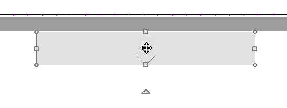
- Use Select Objects
 to move and position the objects to your liking.
- With the millwork object selected, click on the Open Object
 edit button to open the Millwork Specification dialog:
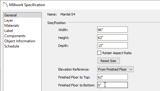
- Specify the Width, Height, and Depth of the object.
- Set the Finished Floor to Top/Bottom values to your liking.
- Make any other desired modifications to the millwork object, then click OK.
Adding molding to the mantel
-
Zoom
 in on the area of your plan where you would like to add molding.
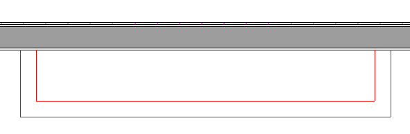
- Select Build> Trim> Molding Line
 from the menu, then click and drag to create several connected lines. This will form an open molding polyline.
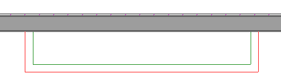
- In this example, the molding polyline displays in red around the Mantel 4 object found by navigating to Core Catalogs> Architectural> Millwork> Mantels, Lintels, & Sills> Surround.
- You may find it helpful to draw the edges longer than necessary to start, and then use the edit handles to adjust the shape and size of the polyline once it is drawn.
- Depending on your plan, you may also find it helpful to temporarily toggle off Object Snaps
 .
.
- Using the Select Objects tool, click on the newly created molding polyline, then select the Open Object edit button .
- On the General panel of the Molding Polyline Specification dialog, specify the Height of the polyline which will represent the bottom edge of the mantel when finished.
In this example, the Height is set to 62".
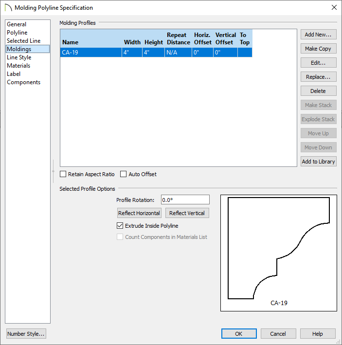
- On the Moldings panel:
-
Click the Add New button and browse the library to select a molding profile.
-
Specify the desired Height and Width of the profile.
-
Make sure that the To Top column is unchecked.
-
Add additional molding profiles and use the Auto Offset checkbox as necessary to create a stacked look.
-
Click OK to close the dialog and finish creating the molding polyline.
- Select 3D> Create Orthographic View> Wall Elevation
 from the menu, then click and drag a camera arrow towards the fireplace to see the results so far.
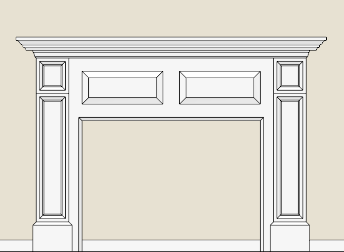
- Add a hearth and accessories to your fireplace, then create a Camera
 view to see the results.