The information in this article applies to:

QUESTION
I am an experienced Chief Architect software user and would like to design a structurally detailed seaside home on pilings. How can I do this?

ANSWER
Chief Architect is designed to allow you to quickly model conventionally framed structures. A structure on pilings, however, does not fall into the category of conventional framing, so when drawing such a plan, we need to use Chief's framing tools creatively.
This article assumes that the reader is familiar with and comfortable using default settings, creating and using custom layers, and using the manual framing and CAD editing tools.
There are a number of distinct tasks involved in this project:
Before starting work on any drawing, it is important to set up the correct default settings – particularly for the structural aspects of the plan.
As you set up your defaults, you can also set up defaults for door styles and materials for roofing, casing, doors and other items. However, only structural defaults are discussed in this example.
To prepare to draw the structure
- Select Edit> Default Settings
 from the menu to open the Default Settings dialog.
- To expand a category in the tree list and view its subcategories, click the arrow
 to the left of its name.
- To open the defaults dialog for a line item, click on its name and then click the Edit button, or simply double-click on its name.
- In the Floor 1 Defaults dialog, on the Structure panel, under the Relative Heights heading, specify the desired Rough Ceiling height. In this example, 109 1/8" is used.
- In the Foundation Defaults dialog, on the Foundation panel:
- Select Walls with Footings as the Foundation Type.
- Under the Stem Walls section, specify the Minimum Height as equal to the required top height of the pilings at the building site, plus the thickness of the concrete pad at the base of the pilings. In this example, 148" is used.
- In the Framing Defaults dialog, on both the Foundation and 1st floor panels, under both the Subfloor for Floor and Ceiling Above Floor headings
- Select the radio button beside Lap.
- Specify the Spacing as 16" O.C..
- Specify the Joist Width as 1 1/2".
- Under the Subfloor for Floor heading on each panel, make sure Rim Joist is checked.
- While still in the Framing Defaults dialog:
- On the Beams panel, click on the Edit Floor Beam Defaults button. Specify the Depth as 11 1/4", Width as 3", the Type as Lumber and click OK.
- Under the Beam Options, select the radio button beside Under Joists and the Align Exterior with radio button beside Main Layer.
- On the Posts panel, click on the Edit Post Defaults button. Specify the Type as Lumber, set the Post Size Widths both as 12".
- Under the Post Footings heading, specify the Height Above Floor, Thickness and Width values as 0". This will prevent footings from being created.
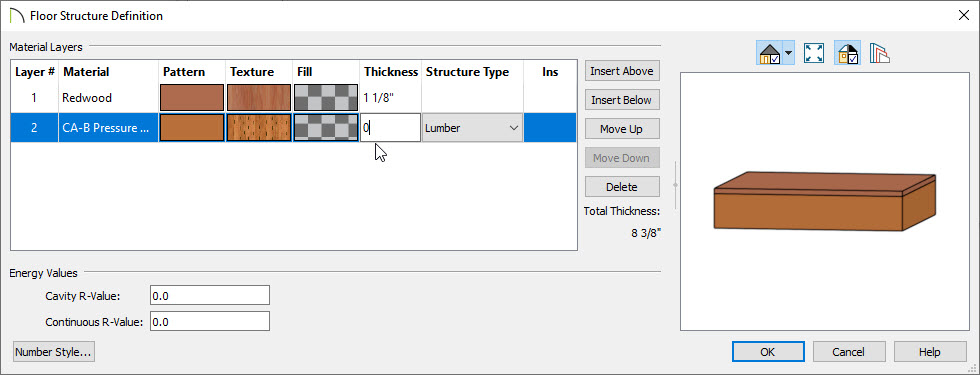
- In Default Settings, expand Floors and Rooms, and select Floor/Ceiling Platform. In the Floor/Ceiling Platform Defaults dialog, click the Floor Structure edit button and specify:
-
Layer 1 as 1 1/2" of OSB Hrz.
-
Layer 2 as 9 1/4" of CA-B Pressure Treated Lumber.
- Use the drop-down menu for Structure Type on Layer 2 to use Lumber.
- In Default Settings, expand Floors and Rooms, and select Room Types. Select Deck and click Edit. In the Deck Room Type Defaults dialog, on the Structure panel:
- Click the Planks, Joists Edit button, specify the desired deck planking thickness and material for Layer 1, and set the thickness for Layer 2 to zero.
- Click OK to save these default settings.
- While still in the Deck Room Defaults dialog, on the Deck panel:
- Uncheck Automatically regenerate deck framing.
- Check Keep deck framing after the deck room is deleted.
- Under the Deck Planking heading, uncheck Automatic and set the Plank Direction to 90°.
- Under the Deck Joists heading, specify the Joist Width as 1 1/2", the Joist Spacing as 16", and the Joist Direction as 0°.
- On the Deck Support panel, uncheck Deck Beams, Deck Posts, and Deck Post Footings.
- In the General Wall Defaults dialog, uncheck Show Wall Length When Editing.
- In both the Exterior/Interior Wall Defaults dialogs, specify the wall types that you require for your project.In this example, the wall types Siding-6 and Interior-4 are used.
- In the Deck Railing Defaults dialog:
- On the Rail Style panel, check the box beside No Half Post at Wall.
- On the Newels/Balusters panel, set the Newel/Posts Width to 1 1/2".
In conventional framing, floor platforms and decks often use different floor platforms with different joist depths, directions, and even materials. When they do not, however, you can save time by automatically generating joists within a temporary shell.
To define the platform perimeter
- Select Build> Wall> Straight Exterior Wall
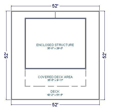
 from the menu and draw walls to define the entire raised platform - including the enclosed building and all decks. In this example, the platform perimeter is 52' x 52'.
- Select Tools> Layer Settings> Display Options
 and turn on the display of the Walls, Main Layer Only layer.
- Select Build> Framing> Framing Reference Marker
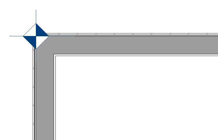
 , then click to place a marker at one of the corners of the structure. In this example, the marker is positioned at the wall intersection in the upper left corner of the structure, on the wall's framing layer.
- Click the Select Objects
 button, then click just outside of one of the walls to select the Exterior Room.
- If you select the wall instead, click the Select Next Object
 edit button or press the Tab key on your keyboard.
- With the Exterior Room selected, click the Make Room Polyline
 edit button to create a polyline around the outside of the walls.
- With the newly created Room Polyline selected, concentrically resize it so it follows the outside of the wall's main layer.
- To do this:
- Zoom in on one of the wall corners.
- Hold down the C key on your keyboard. This is the keyboard hot-key for temporarily enabling the Concentric Edit Behavior.
- Drag the corner handle of the Room Polyline inward until it snaps to the wall's main layer intersection.
- With the Room Polyline still selected, select Edit> Copy
 from the menu.
- Return to the Layer Display Options
 and turn off the Walls, Main Layer Only layer so that all of the wall layers display again in floor plan view.
In conventional framing, the main floor level is built directly on stem walls, a slab, or piers located close to the ground. This application calls for a main floor level to be located many feet above the terrain and supported by pilings,or posts, which must be placed manually. Before these objects can be created, space must be allotted for them in the model.
To create space for the supporting structure
- Select Build> Floor> Build Foundation
 from the menu.
- Choose to Derive new foundation plan from the 1st floor plan.
Do not create a blank new floor.
- Delete the newly created foundation walls on Floor 0.
- Select Edit> Paste> Paste Hold Position
 from the menu to paste a copy of the Room Polyline directly below its original location on Floor 1.
- Select Terrain> Create Terrain Perimeter
 from the menu. The terrain perimeter will be 100' deep and 62' wide, or 10' wider than the structure defined on Floor 1.
- Select Terrain> Terrain Specification
 . On the General panel of the Terrain Specification dialog:
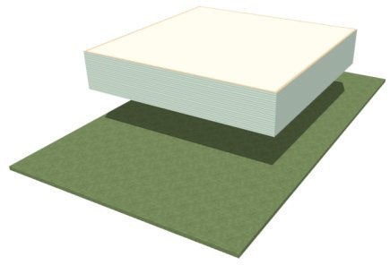
- Under the Building Pad heading, uncheck Automatic and set the Subfloor Height Above Terrain to equal the top height of the pilings plus the thickness of the platform. In this example, 155 3/4" (144" piling height+ 1" pad elevation + 10 3/4" platform thickness) is used.
- Under the Clipping heading, uncheck Hide Terrain Intersected by Building, then click OK.
- Select 3D> Create Perspective View> Perspective Full Overview
 from the menu to see the results so far.
- Select File> Close View when you are finished to return to floor plan view.
With the perimeter defined and vertical space for the structure created, the platform joists can now be generated
To generate the platform joists
- Select Build> Framing> Joist Direction
 from the menu, then click and drag to draw a Joist Direction line in the direction that you want your joists to run.
- In this example, the Joist Direction line is drawn horizontally, or parallel to the side of the building that faces the ocean.
- When prompted to turn on the Framing, Bearing Lines layer, click Yes.
- Select Build> Framing> Build Framing
 .
.
- On the Foundation panel of the Build Framing dialog, check Build Floor Framing and click OK.
- When prompted to turn on the display of the Framing, Floor Joists layer, click Yes.
- Examine the floor joists to make sure they meet your needs. At this point, you can turn off the Framing, Floor Joists layer and Delete
 the Joist Direction Line.
- Go Up One Floor
 to Floor 1 and delete the Framing Reference Marker that you placed earlier, as well.
- Create a Perspective Framing Overview
 to view the results.
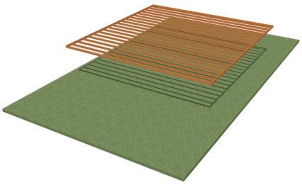
- To better see the joist's height, turn on the Terrain Perimeter layer while the framing overview is active if it's display is not already enabled.
- Close the view when you are finished.
The floor joists were generated using a temporary shell to define the platform. Once they are in place, the temporary shell can be replaced by the walls and railings of the actual structure.
To position the walls and deck railings
- Select each of the shell walls and use dimensions to move them so that they can serve as the exterior walls of the enclosed structure. In this example, the back or street side wall of the structure is moved 4' inward, both side walls are moved 8' inward, and the front or ocean side wall is moved 18' inward.
- Create an Exterior Room Polyline for the resized structure using the steps described earlier:
- Turn on the Walls, Main Layer Only layer.
- Select the Exterior Room and click the Make Room Polyline
 edit button.
- Concentrically resize the polyline so it snaps to the outside of the wall's Main Layer.
- Turn the Walls, Main Layer Only layer off again.
- Select Build> Railing and Deck> Straight Deck Railing
 from the menu, then click and drag to draw Deck Railings that snap to the Exterior Room Polyline created previously. An Invisible Wall, or Room Divider, will automatically connect the outer deck railing from the walls of the enclosed structure to prevent an "island" room from being created. This is expected program behavior.
- Create an Exterior Room Polyline for the Deck Railing, as described above.
- Draw additional Deck Railing to define a covered deck area.
- Make sure that the railing snaps to the Main Layer of the enclosed structure's exterior walls.
- In this example, the covered deck area will extend out 10' from the enclosed structure.
- Specify the Deck Railings that define the covered deck area as Invisible on the General panel of the Deck Railing Specification dialog.
- Select CAD> Lines> Draw Line
 from the menu, then click and drag to draw a line along the outside edge of the Invisible Deck Railing that faces the ocean side. Edit the CAD line's length as needed so it snaps to both ends of the Deck Railing without extending past it.
- With the Draw Line
 tool still active, select all of the CAD objects on Floor 1 and send a copy to the clipboard.
-
Zoom
 out so you can see the entire drawing.
- Select CAD> Lines> Draw Line
 from the menu
- Hold down the Shift key, then click and drag to draw a large rectangle around the entire drawing. The Status Bar should show 4 objects currently selected.
- Select Edit> Copy
 from the menu.
- Go Down One Floor
 and select Edit> Paste> Paste Hold Position
  to create a copy of the selected Room Polylines and CAD Line on Floor 0, directly below the originals.
Once the walls and deck railings are in their final locations, pilings can be placed to support them. The CAD objects copy/pasted from Floor 1 will serve as helpful references.
To create the pilings
- Select Edit> Preferences
 if you're on a Windows PC or Chief Architect> Preferences
  if you're on a Mac. On the Behaviors panel of the Preferences dialog, specify the Concentric Jump distance as 3", then click OK.
- Click the Select Objects
 button, then select the smaller Room Polyline associated with the enclosed structure and concentrically resize it 6" smaller. To do this:
- Zoom in on one of the polyline corners.
- Hold down the C key on your keyboard.
- Click and drag the corner edit handle slowly inward until you see it snap to the Concentric Jump increment two times, for a total of 6".
- Select Build> Framing> Post
 from the menu, then click to place a single Post centered at the upper left corner of the smaller Room Polyline copy/pasted from Floor 1.
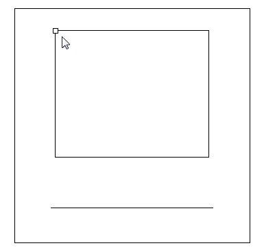
- When Object Snaps
 are enabled, the Post's center point will snap to the corner of the polyline.
- If prompted to turn on the Framing, Posts layer, click Yes.
- With the Post tool still active, click on the post and click the Open Object
 edit button to open the Framing Specification (Post) dialog:
- On the General panel, select Lock Top Height and specify the Total Height as 145".
- On the Line Style panel, click the Define button under the Layer heading to open the Layer Display Options. Turn off the display of the Framing, Floor Joists layer if it is still turned on, and create a new layer called Framing, Pilings, select it, and click OK.
- On the Fill Style panel, select Solid from the Pattern - Type drop-down list, click the Appearance - Color color bar and choose white.
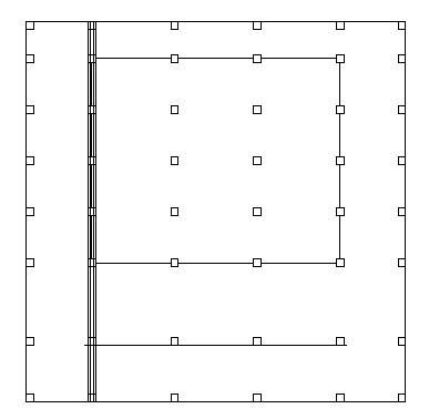
- With the post still selected, use the Multiple Copy
 edit tool to create an array of pilings under the enclosed structure. To do this:
- Click the Multiple Copy
 edit button.
- Click the Multiple Copy Interval
 edit button.
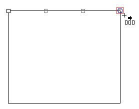
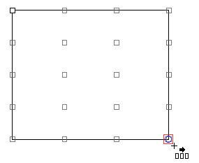
- In the Multiple Copy dialog, click the radio button beside Evenly Distribute Copies When Dragging, then specify the desired number of Primary and Secondary copies and then click OK. In this example, 3 and 4 are used, respectively.
- Right-click and drag from left to right, stopping when the editing preview snaps to the top right corner of the polyline. Release the mouse button to create a row of four pilings.
- Right-click again and drag down to the bottom right corner. Release the mouse button to create four more rows of pilings identical to the first.
- Group-select the top horizontal row of pilings use the Copy/Paste
 edit tool and Move
  edit handle to create another row of pilings aligned with the original and snapped inside the large outer Room Polyline. With Object Snaps
  on, the pilings will snap to the polyline edge at their centers. If this occurs, leave them group-selected, Zoom
  in, and adjust their position.
- With the newly copied pilings selected, increase their top heights so they extend through the outer Deck Railings and act as newel posts. To do this:
- Click the Open Object
 edit button.
- On the General panel of the Framing Specification (Post) dialog, select Lock Bottom Height and specify the Top Height as 36".
- Repeat steps 6 and 7 to create two copies of the bottom row of pilings: one aligned inside the bottom edge of the outer Room Polyline and one aligned with the CAD line representing the edge of the covered deck area. When you add a roof over the covered deck area later on, you can adjust the top heights of the pilings defining that area so they support the roof.
- Use this same procedure to create two additional vertical rows or columns: one aligned inside the left edge of the outer Room Polyline, and one aligned with the right edge.
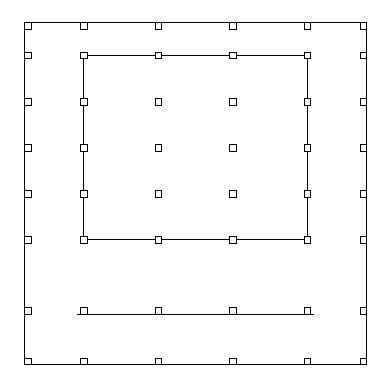
- Create a Perspective Framing Overview
 and turn on the Framing, Pilings layer to view your progress. When you are finished, Close the view.
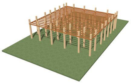
With the pilings in place, pairs of stringers can be added to their sides, directly under the platform joists. Stringers typically sit on a notch at the top of the pilings. In Chief Architect, we will simply position the stringers inside the perimeter of the pilings.
To create the stringers
- Select Build> Framing> Floor/Ceiling Beam
 from the menu, then click and drag vertically to draw a stringer along the right side of the pilings under the left side of the enclosed structure.
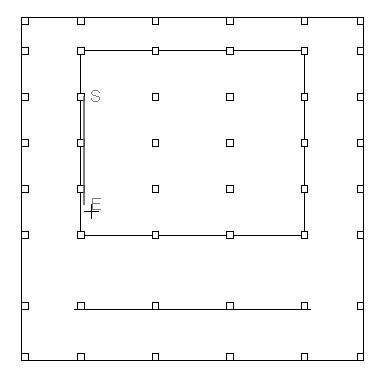
- Make sure that this stringer is drawn entirely within the Room Polyline representing the enclosed area. Do not extend it into the Deck area at this time.
- By default, beams will snap to objects like posts at the midpoint of the beam's end. For the purposes of this example, this is fine.
- If prompted to turn on the Framing, Floor Beams layer, click Yes.
- Resize the stringer so that it extends along all of the pilings and reaches the top and bottom edges of the outermost deck pilings.
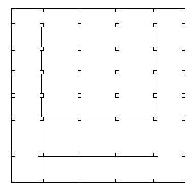
- Click on the stringer to select it, then click the Open Object
 edit button to open the Framing Specification (Floor Beam) dialog:
- On the Line Style panel, click the Define button under the Layer heading, create a new layer named Framing, Floor Stringers, select it, and click OK.
- On the Fill Style panel, specify a Solid grey fill.
- With the stringer still selected, click the Transform/Replicate Object
 edit button. In the Transform Replicate Object dialog:
- Check the box beside Move.
- Specify the X Delta value as a negative number equal to half the Thickness of the beam - in this example, -1 1/2", then click OK.
- If your project will require presentation views that include the stringers, instead specify 1 7/16" as the X Delta value so the stringers and piling materials do not Z-fight in camera views.
- With the stringer still selected, use the Copy/Paste
 and Reflect About Object
  edit tools to create a copy on the other side of the adjacent pilings. To do this:
- Click the Copy/Paste
 edit button.
- Click the Reflect About Object
 edit button.
- Click once on one of the adjacent pilings.
- Use the Copy/Paste
 and Point to Point Move
  edit tools to create a pair of stringers on either side of all the vertical rows of pilings. To do this:
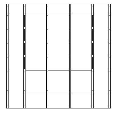
- Select one of the stringers, hold down the Shift key, and then click on the other stringer to select them both.
- Click the Copy/Paste
 edit button.
- Click the Point to Point Move
 edit button.
- Click on the top left corner of the piling at the top of the row between the stringers.
- Click on the top left corner of the piling at the top of the next row.
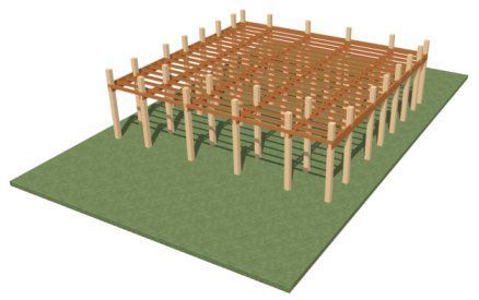
- Create a Perspective Framing Overview
 and turn on the Framing, Floor Stringers layer to view your progress. When you are finished, close the view.
The last structural item that needs to be added on Floor 0 is a concrete pad.
To create the pad
- Click the Select Objects
 button, then click on the smaller Room Polyline associated with the enclosed structure.
- Click the Convert Polyline
 edit button, and in the Convert Polyline dialog, select Sidewalk (Perimeter) and click OK. Alternatively, you could select Slab; however, Sidewalks automatically follow the terrain without requiring you to calculate the needed height relative to the floor on Floor 1.
- On the General panel of the Terrain Path Specification dialog, which opens next, confirm that the Height is 1" and click OK.
-
Zoom
 in on the newly created Sidewalk and Concentrically Resize it larger as described above by at least 9", or three Concentric Jump increments.
- When you are finished, the remaining Room Polyline and CAD Line can be deleted.
- Since Preference settings are global, it is a good idea to return to Preferences
 and set the Concentric Jump value back to 0".
To generate the deck planking
- Go Up One Floor
 to Floor 1 and click in an empty space in one of the Deck rooms to select it.
- Hold down the Shift key and click in the other Deck room to select them as a group.
- Click the Open Object
 edit button and on the Deck panel of the Room Specification dialog, check the box beside Automatically regenerate deck framing and click OK.
- Create a Perspective Full Overview
 to see the results. Turn on the Framing, Pilings and Framing, Floor Stringers layers so that they can be seen, as well.
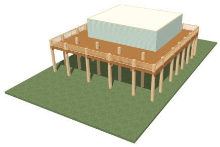
At this point, the foundation structure and main level floor platform are complete, and you can now add interior walls, doors and windows, stairs, a roof - and even a second floor. Using the information provided in this tutorial, you should now be prepared to apply this knowledge to your designs created on pilings.


 from the menu to open the Default Settings dialog.
 from the menu and draw walls to define the entire raised platform - including the enclosed building and all decks. In this example, the platform perimeter is 52' x 52'.
 and turn on the display of the Walls, Main Layer Only layer.
 , then click to place a marker at one of the corners of the structure. In this example, the marker is positioned at the wall intersection in the upper left corner of the structure, on the wall's framing layer.
 button, then click just outside of one of the walls to select the Exterior Room.
 edit button or press the Tab key on your keyboard.
 edit button to create a polyline around the outside of the walls.
 from the menu.
 and turn off the Walls, Main Layer Only layer so that all of the wall layers display again in floor plan view.
 from the menu.
 from the menu to paste a copy of the Room Polyline directly below its original location on Floor 1.
 from the menu. The terrain perimeter will be 100' deep and 62' wide, or 10' wider than the structure defined on Floor 1.
 . On the General panel of the Terrain Specification dialog:
 from the menu to see the results so far.
 from the menu, then click and drag to draw a Joist Direction line in the direction that you want your joists to run.
 .
. the Joist Direction Line.
 to Floor 1 and delete the Framing Reference Marker that you placed earlier, as well.
 to view the results.
 edit button.
 from the menu, then click and drag to draw Deck Railings that snap to the Exterior Room Polyline created previously. An Invisible Wall, or Room Divider, will automatically connect the outer deck railing from the walls of the enclosed structure to prevent an "island" room from being created. This is expected program behavior.
 from the menu, then click and drag to draw a line along the outside edge of the Invisible Deck Railing that faces the ocean side. Edit the CAD line's length as needed so it snaps to both ends of the Deck Railing without extending past it.
 tool still active, select all of the CAD objects on Floor 1 and send a copy to the clipboard.
 from the menu
 from the menu.
 and select Edit> Paste> Paste Hold Position
  to create a copy of the selected Room Polylines and CAD Line on Floor 0, directly below the originals.
 if you're on a Windows PC or Chief Architect> Preferences
  if you're on a Mac. On the Behaviors panel of the Preferences dialog, specify the Concentric Jump distance as 3", then click OK.
 button, then select the smaller Room Polyline associated with the enclosed structure and concentrically resize it 6" smaller. To do this:
 from the menu, then click to place a single Post centered at the upper left corner of the smaller Room Polyline copy/pasted from Floor 1.
 are enabled, the Post's center point will snap to the corner of the polyline.
 edit button to open the Framing Specification (Post) dialog:
 edit tool to create an array of pilings under the enclosed structure. To do this:
 edit button.
 edit button.

 edit tool and Move
  edit handle to create another row of pilings aligned with the original and snapped inside the large outer Room Polyline. With Object Snaps
  on, the pilings will snap to the polyline edge at their centers. If this occurs, leave them group-selected, Zoom
  in, and adjust their position.
 edit button.
 and turn on the Framing, Pilings layer to view your progress. When you are finished, Close the view.
 from the menu, then click and drag vertically to draw a stringer along the right side of the pilings under the left side of the enclosed structure.

 edit button to open the Framing Specification (Floor Beam) dialog:
 edit button. In the Transform Replicate Object dialog:
 and Reflect About Object
  edit tools to create a copy on the other side of the adjacent pilings. To do this:
 edit button.
 edit button.
 and Point to Point Move
  edit tools to create a pair of stringers on either side of all the vertical rows of pilings. To do this:
 edit button.
 edit button.
 and turn on the Framing, Floor Stringers layer to view your progress. When you are finished, close the view.
 button, then click on the smaller Room Polyline associated with the enclosed structure.
 edit button, and in the Convert Polyline dialog, select Sidewalk (Perimeter) and click OK. Alternatively, you could select Slab; however, Sidewalks automatically follow the terrain without requiring you to calculate the needed height relative to the floor on Floor 1.
 in on the newly created Sidewalk and Concentrically Resize it larger as described above by at least 9", or three Concentric Jump increments.
 and set the Concentric Jump value back to 0".
 to Floor 1 and click in an empty space in one of the Deck rooms to select it.
 edit button and on the Deck panel of the Room Specification dialog, check the box beside Automatically regenerate deck framing and click OK.
 to see the results. Turn on the Framing, Pilings and Framing, Floor Stringers layers so that they can be seen, as well.