QUESTION
I would like to create a custom fireplace with an insert, hearth and mantel. How can I do this?

ANSWER
Creative combinations of different objects such as fixtures, soffits, walls and wall openings allow you to create a wide variety of fireplace and chimney designs.
To build a chase for a fireplace insert
- Select Build> Wall> Straight Wall Interior
 from the menu and draw three walls to form the chase for your fireplace and chimney.
Do not worry about the exact placement of the walls right now, they can be moved into position accurately in a moment.
- Select CAD> Dimension > Interior Dimension
 from the menu, and drag an Interior Dimension line across the room, beginning at one wall and dragging straight through the side walls of the chase.
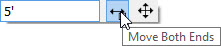
- Click on the left side wall of the chase to select it, then click on the dimension that displays between it and the wall to the left and in the Move Object Using Dimension in line text box, specify the desired distance between these two walls, then press the Enter key on your keyboard.
- Repeat this process with the wall on the right side of the chase and the wall forming the front of the chase.

- Adjust the lower wall to set the desired depth of the chase.
To place an insert into the chase
- Select Build> Window> Window
 from the menu and click on the front wall of your chase to place a window at that location. This window will be used to create a wall opening in which an insert can be modeled in.

- With the window still selected, click the Open Object
 edit button to display the Window Specification dialog:
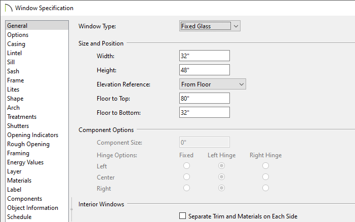
- On the General panel, click the Window Type drop-down arrow and select Fixed Glass from the list.
If you already know the size and height you want the opening to be, you can specify it here.
-
- On the Casing panel, uncheck Use Interior Casing.
- On the Sill panel, uncheck Use Interior Sill.
-
- On both the Sash and Frame panels, specify any widths desired.
-
- On the Materials panel, click on Glass, click the Library Material... button, then browse and select a Fire material.
For the purposes of this example, we browsed to Chief Architect Bonus Catalogs> Modern Fireplaces> Materials & Images> Materials> Fireplace Fire.
You can choose the other materials now if you like, or wait until later. They can, of course, be changed at any time.
-
- Click OK to close the Select Library Object dialog and apply your changes.
- Click OK once more to close the Window Specification dialog and apply all of these changes.
- Select View> Library Browser
 from the menu to open the Library Browser window and use the Search feature, or browse to Chief Architect Core Catalogs> Interiors> Accessories> Fireplace Accessories.
Select the fireplace screen you wish to place, then click once directly in front of your window in your floor plan to place the selected screen in your plan.

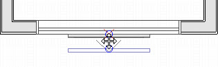
- If necessary, use the Select Objects
 tool and select the fireplace screen, then use the Move
  edit handle to drag the screen so that it is directly in front of the window forming the insert opening.
- Select 3D> Create Orthographic View> Cross Section/Elevation
 , click in front of the fireplace and drag a camera view in the direction of the window and screen, keeping the camera arrow perpendicular to the front wall.
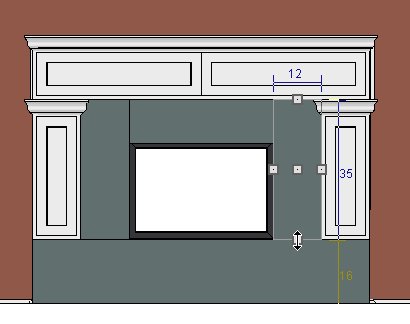
- In this cross section view:
- If the screen is not visible, in the main menu click on Tools> Layer Settings> Display Options
 , and ensure that the "Furniture, Interiors" layer is checked to display.
-
If necessary, select the window and resize the opening as desired using the edit handles that display.
-
- Click on the fireplace screen to select it, move and resize it using the edit handles so that it fits inside the frame of the window. Hold Ctrl/Command on your keyboard if the screen is snapping to undesirable locations.
- When you are satisfied with the appearance of the frame and screen, close the camera view and return to floor plan view.

- In floor plan view, select Window> Zoom
 from the menu, then click and drag a rectangular marquee around the fireplace insert chase, including the screen in the selection.
- Click on the fireplace screen to select it, hold down the Ctrl/Command key on your keyboard and drag the screen into the window using the Move edit handle, then click the Center Object
 edit button and click inside the chase 'room' area to center it within the Window.

If the screen snaps to the outside edge of the window opening, click the Open Object edit button and increase the Depth, or thickness, of the screen to 6 inches, click OK, then try again.
Many custom objects can be designed using the Soffit tool, which is a child of the Cabinet Tools.
To add a hearth
- Select Build> Cabinet> Soffit
 from the menu, then click once in the plan to create a soffit.
- Select the soffit and use its edit handles to move the soffit into position in front of the fireplace and resize it as needed.

- With the soffit still selected, click the Open Object edit button. In the Soffit Specification dialog:
- On the General panel, specify the desired Height of the hearth, which should be near the bottom of the insert opening.
-
- Specify the Floor to Bottom distance as 0, since this hearth should rest on the floor.
-
- On the Materials panel, click on the word Soffit, then click the Select Material button and browse the Materials library to find an appropriate material for the hearth.Remember that this material can be changed at any time.
-
- Click OK to close the dialog and apply your changes.
- You can create a cap for your hearth using a second, thinner soffit placed on top of the first if you so desire.

The advantage to using a Soffit instead of a 3D/Polyline Solid for this instance is that it will pick up the Base Molding from the room, and you can add additional moldings to it as well, such as a curved edge molding.
Because cabinets feature front items such as drawers, doors and panels, the Full Height Cabinet tool, which is another child of the Cabinet Tools, can be used to create customized mantels and square columns beneath.
To add a mantel with columns
- Select Build> Cabinet> Full Height Cabinet
 from the menu, then click to create a full height cabinet in front of the fireplace.
- Click on the full height cabinet to select it then click the Open Object edit button.
- In the Full Height Cabinet Specification dialog:
- On the General panel, specify the Depth of your mantel, as well as the Height, Width, and Finish Floor to Bottom distance, and uncheck Toe Kick".
- On the Front/ Sides/ Back panel, click on the bottom door of the cabinet in the preview image and click on the Delete button to remove this face item. Repeat this process on the Opening that was left behind, to remove it as well. Then click on the remaining door and specify it as a Door Panel in the Item Type drop-down list.
- On the Door/Drawer panel, select None from the Door Handle and Drawer Handle drop-down lists.
-
- Click OK to close the dialog and apply your changes.
- With the full height cabinet still selected, use the Move edit handle to move it into position over the hearth.
- Using the same process, follow steps 1-3 to create pillars to fill the gap between the hearth and mantel and to create the mantel itself.
- Once your first pillar is in place, select CAD> Lines> Draw Line and draw a line down the center of the mantel/hearth.
-
- Click to select the line, then click the Center Object edit button and click inside the chase 'room' area to center it.
-
- Click the Select Object tool, select the pillar and click Copy Object
 tool, then Reflect About Object
  , and click on the line to create a copy of the pillar on the other side of the mantel.
-
- Select and delete the CAD Line.
- Create a cross section view of your mantel to view your progress, and make any necessary adjustments. 3D> Create Orthographic View> Cross Section/Elevation from the menu and click and drag a camera view in the direction of the fireplace.
- Use the edit handles to adjust the size and position of the mantel and columns as needed.

To create a chimney
- Select Build> Cabinet> Soffit from the menu, then click once in the plan to create a soffit.
- Select the soffit to display its edit handles and use those handles to move the soffit into position inside the chimney chase and then resize it so that it fills the interior space of the chase 'room'.
- To extend the soffit through the exterior wall so that it displays on the exterior of your plan, press the Ctrl/Command key on your keyboard and then use the Move edit handle to move the soffit through the exterior wall at the back of the chase 'room'. You may need to adjust the size again afterward.
- With the soffit still selected, click Open Object edit button. On the General panel of the the Soffit Specification dialog:
- Specify a Height that will place the chimney top at an appropriate height above the roof.
-
- Specify the Floor to Bottom distance at -18 so that the soffit reaches through the floor platform to the ground level outside.
-
- Click OK to close the dialog and apply your changes.
- Select 3D> Create Perspective View> Perspective Full Overview
 from the menu to create a bird's-eye view of the exterior of your plan, including the chimney, and notice that the chimney displays a beige drywall material. We can select a more appropriate material for the chimney using the Material Painter.
To create the appearance of a masonry chimney, you can apply a stone, block or brick material to the chase that you created using Interior Walls in the walls' specification dialog. If you want to use a second material to surround the fireplace opening, use the Soffit tool.
To apply materials to the chase walls and fireplace surround
- Click on the wall that defines the front of the chimney chase 'room' to select it, and then click the Open Object edit button.
- On the Materials panel of the the Wall Specification dialog, click on the words Exterior Surface, then click the Select Material button and browse the Materials library to find the material you prefer.
- If you would like to, repeat this process with the walls defining sides of the chase 'room.'
- To create a surround for the fireplace opening, begin by placing a Soffit in your plan.
- With the soffit selected, use the edit handles to reduce its width to one inch or so, depending on the material you would like to use for your surround. Use the Move edit handle to position the soffit directly against the front wall of the chase.
- Select 3D> Create Orthographic View> Cross Section/Elevation from the menu and drag a camera view in the direction of the window and screen, keeping the camera arrow perpendicular to the front wall. In this cross section view:
- In this cross section view:
- Click on the soffit to select it and click the Copy/Paste edit button. Click the Sticky Mode
 edit button, then click once in an empty area of the front wall of the chase to create a copy of the soffit and click again in another empty area to create a second copy.
-
Click the Select Objects arrow tool and edit the size, shape and location of each soffit so that they form a complete surround for the fireplace opening.
- Select 3D> Material Painter> Material Painter
 from the menu and apply the desired material to the soffits forming your fireplace surround.