QUESTION
I would like to design a structure in which I need to have two walls side-by-side for bearing, sometimes known as marriage walls. How can I model this in Chief Architect?

ANSWER
Creating marriage walls in Chief Architect is easily done by creating a custom Wall Type and using the Double Wall directives located on the Structure panel of the Wall Specification dialog. The Double Wall options specify how a selected straight wall frames when it is parallel to, and touching a second wall.
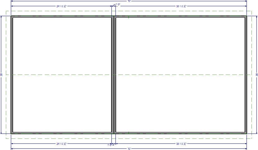
For the purposes of this example, a basic shell of the plan below is used.
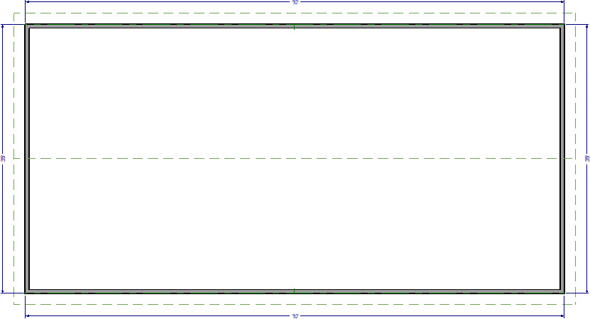
Both the left and right exterior walls are set to be full gable walls and the roof has been built creating a basic gable roof style. The default Interior-6 wall type is used for the two interior walls.
To use marriage walls
- Navigate to Build> Wall> Define Wall Types
 and in the Wall Type Definitions dialog that displays:
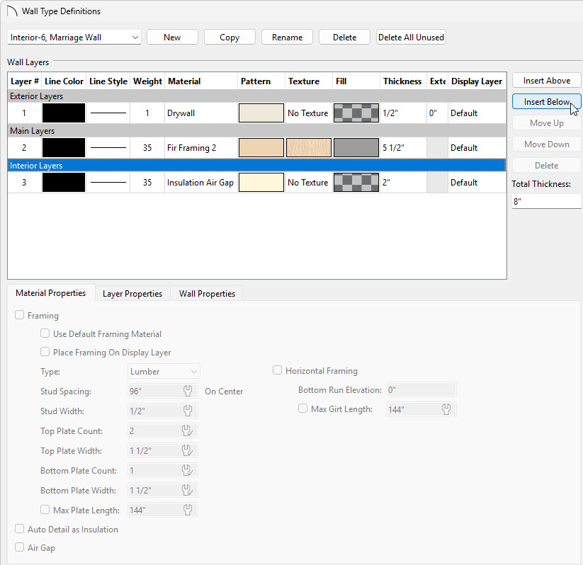
- Select a Wall Type from the drop down that you would like to start with.
In this example Interior-6 is used.
- With your Wall Type selected click Copy to create a copy of your Wall Type and then rename it.
In this example, the name "Interior-6, Marriage Wall" is specified.
- Select the Drywall layer underneath of the Interior Layers and Delete it.
- Click Insert Below to insert an Insulation Air Gap layer.
- Set the Thickness of your air gap layer to your desired thickness.
In this example, 2" is used.
- Click OK when you're done making changes.
- Select Build> Wall> Straight Interior Wall
 , then click and drag to draw the two walls near each other in the same Start to End direction.
- After they are drawn, use the Select Objects
 tool to select the first wall, hold down the Shift key on your keyboard, then click on the second wall so that both walls are selected.
- With both wall selected use the Open Object
 edit tool to display the Wall Specification dialog for both of these walls.
-
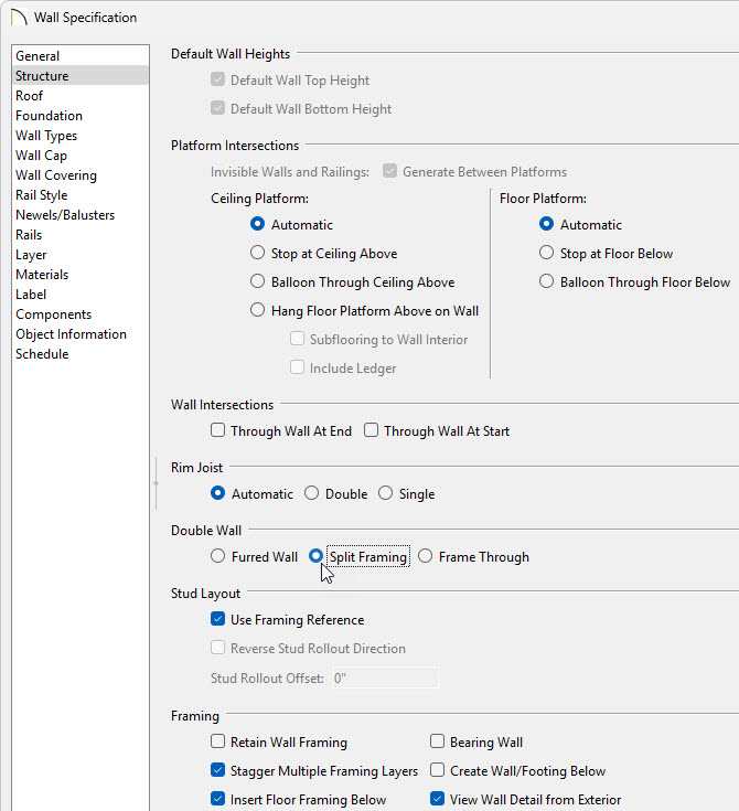
On the Structure panel of the Wall Specification dialog that appears, select the Split Framing radio button under the Double Wall category.
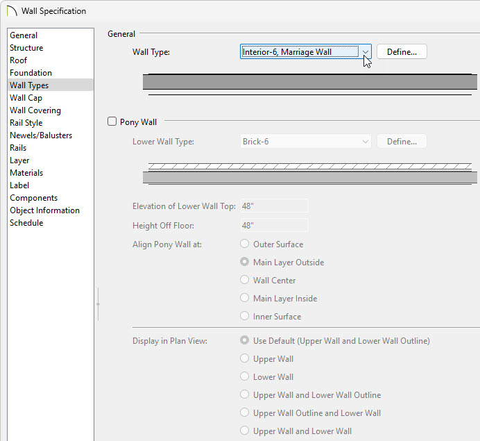
- On the Wall types panel use the drop down to select the "Interior-6, Marriage Wall" and click OK.
- Using the Select Objects tool select the wall who's air gap layer is facing the wrong direction and use the Reverse Layers
 edit tool to flip the wall.
- Use their Move
 edit handles to move them into contact with one another.
![]()
- Select Build> Floor> Build Foundation
 to display the Build Foundation dialog:
-
On the Foundation panel make any necessary changes to how your foundation will be built and click OK.
-
In this example we keep all of the standard defaults.
- In the New Floor dialog, choose to Derive new Foundation plan from the 1st Floor plan, then click OK.
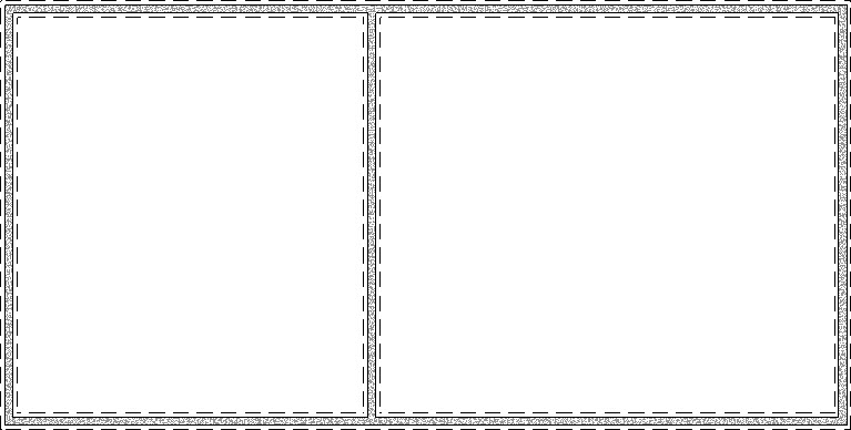
- Chief Architect will now display the foundation level, also known as Floor 0, and a single Foundation Wall will have been built beneath the double wall above.
- While still on the Floor 0 level, select Build> Framing> Build Framing
 from the menu.
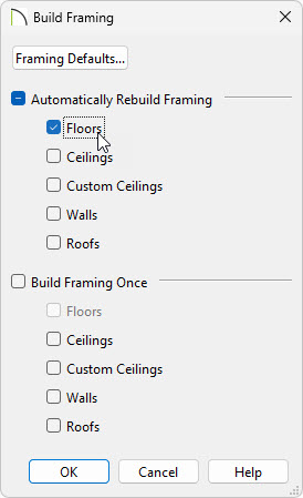
- In the Build Framing dialog check the box for Floors underneath either Automatically Rebuild Framing or Build Framing Once and click OK to automatically build your floor framing.
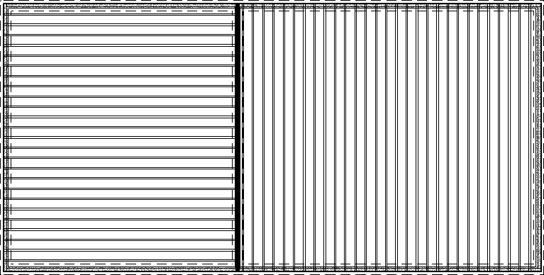
- On the foundation level, you should now be able to see that the floor framing for each side of the double wall on the structure has framed independently.
If the floor framing does not generate to your liking, consider using the Joist Direction tool to define the direction that joists are laid out. For more information on this tool, please see the Related Articles section below.
- You are now ready to continue with your design, including building the wall framing or manually editing any framing members if necessary.
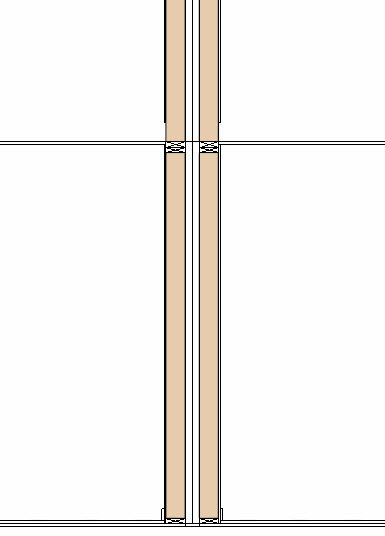
The cross section view above is an example based on the basic plan used in this article. Recall that building your framing is one of the last steps when designing a plan in Chief Architect, after adding interior walls, doors, doorways, windows, etc.