QUESTION
Is there a way that I can create a custom door object and add it to my library in Chief Architect?

ANSWER
Custom objects, including doors, can be created using a combination of shapes. Once a custom door object has been defined to your liking, the Convert to Symbol tool can be utilized to create a door symbol that can take on door attributes.
In this article, we will discuss how to use CAD to create the initial shape of a custom door, followed by converting the CAD into 3D/polyline solids, adding trim, and lastly, creating the symbol.
To form the initial shape of the door
- In a blank plan, select 3D> Create Orthographic View> Cross Section/Elevation
 from the menu, then click and drag to create an elevation view.

- In the elevation view, select CAD> Boxes> Rectangular Polyline
 from the menu, then draw a polyline that will be the size of the door.
In this example, we created a polyline that's 36" wide by 80" tall.
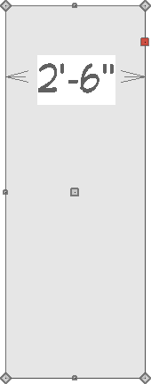
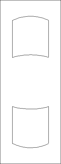
- Create a second polyline to serve as the first door panel.
In this example, we created a polyline that's 18" wide by 18" tall.
- Select the top edge of the polyline created in Step 3, then click the Change Line/Arc
 edit tool.
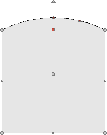
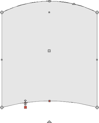
- Repeat this process for the bottom edge, then use the small triangle edit handle to curve the arc upward, as shown below.
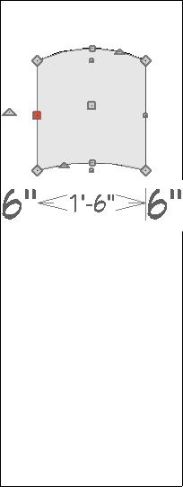
- Move this polyline to be inside of the polyline representing the door.
In this example, the polyline representing the panel is placed roughly 7-8" down from the top edge of the door and 6" in on either side.
- With this polyline still selected, click the Copy/Paste
 edit tool, click the Reflect About Object
  secondary edit tool, hover over the center of the door until you see the reflect line running horizontally, then click to to place a reflected copy of the panel at the bottom of the door.
You can also create a copy of the panel, then use the Move  and Rotate
  edit handles to position it into place.
-
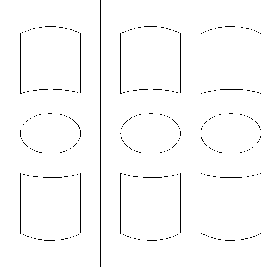
Next, select CAD> Circles> Ellipse
 from the menu, draw an ellipse, then use the Center Object
  edit tool to center it on the door.
In this example, we created an ellipse that's 18" wide by 12" tall.
- Select the three polyline objects inside of the door and use the Copy/Paste edit tool to create copies of these objects beside the door for later use.
Do this twice, as shown below.
Now that we have the general layout of the door panels established, we are ready to convert the objects into 3D/polyline solids.
To convert the components to 3D/polyline solids
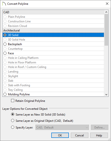
- Select the door outline, which was the first shape created in Step 2 above, click on the Convert Polyline
 edit tool, select the 3D/Polyline Solid option in the dialog that appears, then click OK.
-
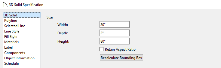
In the 3D/Polyline Solid Specification dialog that opens next, specify an appropriate Depth/Thickness value, then click OK.
In this example, a depth/thickness of 2" is specified. This value will be the thickness of the door.
- Select the three polyline objects that are currently contained inside the door, then click the Convert Polyline edit tool.
For more information on selecting multiple objects at once, please refer to the "Group Selecting Objects" resource in the Related Articles section below.
- In the Convert Polyline dialog that appears, select the 3D Solid Hole option, then click OK.
In X13 and prior versions, select the Polyline Solid option instead, then click OK.
- In the 3D/Polyline Solid Specification dialog that appears next, click OK without making any changes.
In X13 and prior versions, check the Hole in Polyline Solid box, then click OK.
- Now, group select the next set of three polyline objects that we copied, and using the Point to Point Move
 edit tool or the Move edit handle, align them with the newly created holes in your door.
- With the polyline objects still selected, click the Convert Polyline edit tool, convert them to 3D/Polyline Solids, then specify their Depth/Thickness.
In this example, 1/4" is specified as the thickness.
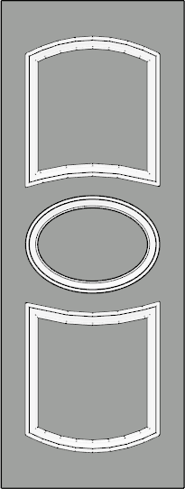
- Return to floor plan view and center the 3D/polyline solids inside the door outline, as shown below. The Center Object edit tool works well for this process.

Now, we are ready to finish door by adding trim to each of the panels.
To add trim to the door panels
- In the cross section/elevation view, select the final set of the three polyline objects that were copied in the first section of this article, click the Convert Polyline edit tool, select the Molding Polyline option in the dialog that appears, then click OK.
In X15 and prior versions, select the 3D Molding Polyline option instead.
- On the Moldings panel of the 3D/Molding Polyline Specification dialog that opens:
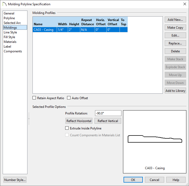
- Choose your desired molding profile using the Replace button.
In this example, CA03 - Casing is used.
- Specify the Width, Height, and any desired offsets.
In this example, a width of 1/4" and a height of 2" are specified.
- Choose whether or not Extrude Inside Polyline is checked.
Molding polyline edges are drawn in a clockwise direction with the molding profile located on the right-hand side of each edge. This places the molding profile on the interior of a closed polyline by default. Unchecking this setting moves the profile to the other side of the polyline edges.
In this example, the setting is unchecked.
In X15 and prior versions, leave this option checked.
- Choose whether or not to rotate and reflect the profile using the Profile Rotation field and Reflect buttons.
In this example, the Reflect Horizontal button has been selected once, and a profile rotation value of -90.0° is specified.
In X15 and prior versions, these changes aren't necessary.
- Return to floor plan view, draw a selection marquee around the molding polylines using the Select Objects
 tool, then use the Move edit handle to move the polylines so they bump up against the outer edge of the door.

- You may need to toggle between floor plan and the cross section/elevation view in order to line the objects up properly.
- Once the molding polylines are in place, use the Copy/Paste and Reflect About Object edit tools in a floor plan view to replicate the trim on the other side of the door. If needed, use the Move and Rotate edit handles to adjust the copied polylines so that they are positioned and oriented correctly.

Now that the door is built, we are almost ready to convert it to a symbol. But before doing so, we should assign the correct materials to the door. If all the pieces of the door object are left with their default material, you may not be able to customize the materials fully as you might wish later on.
To create the door symbol
- Navigate to 3D> Create Perspective View> Perspective Full Overview
 to generate a camera view of the door components.
- Select 3D> Material Painter> Material Painter
 from the menu, select a material of your choosing, then click on the door objects you'd like to apply the material to.
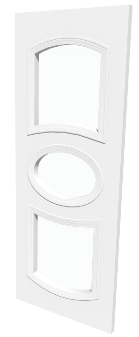
- Repeat Step 2 until all of the door objects have the desired materials applied.
In this example, we have specified the 1/4" 3D/polyline solids that are inside of the door to be glass, and both the trim and the door are set to a white color material.
- Staying within the camera view, select Tools> Symbol> Convert to Symbol
 .
.
You can also group select the door objects and click the Convert Selected to Symbol  edit tool.
- In the Convert to Symbol dialog that displays:
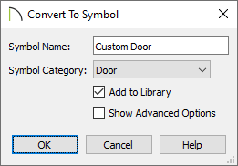
- Specify a Symbol Name for the door.
- Using the Symbol Category drop-down, choose the Door option from the list.
- Check Add to Library.
- Click OK.
-
The door symbol is now located in the User Catalog section of the
Library Browser 
and is ready for use in your plans.
Once a door symbol is placed into a wall, hardware, casing, thickness, as well as other door attributes can be modified in the Door Specification dialog.
You can use any combination of shapes to create a variety of objects and then convert them to the appropriate category depending on your intended use of each object.