When I take a 3D camera view of my plan, the materials don't look right. They appear to flicker on screen when I rotate, and look as though they are showing the materials that should be behind them.
Why is this happening, and how do I fix it so my plan displays correctly?
There are several different potential reasons why you may exhibit this behavior, known as z-fighting. The most common reasons are:
To resolve the issue, we first need to determine the cause. If all of the objects in your plan appear to be exhibiting the behavior, the issue is likely related to one of the first three; either the plan is located too far from the origin, you have an object very far away from your design, or you have an exceedingly large terrain.
 to toggle it on/off.
The most common reason for this would be if you have imported a DWG or DXF file from a third party source in to the program that was located very far from the origin, and then proceeded to draw in this area rather than moving it back to the origin.
 to zoom out so that the entire view fits on the screen.
 , then click and drag a selection marquee around everything in the floor plan.
 edit tool. again to bring the content back into view.
 of the structure to verify that the issue is resolved.
In the future, if you import a DWG or DXF file from an outside source, you'll want to make sure to set it back to the origin before beginning to draw in the structure.
 . to zoom out so that the entire view fits on the screen.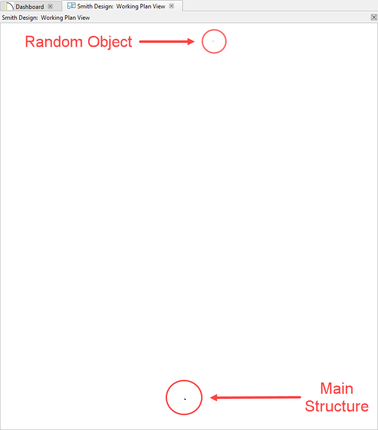
 it, and Delete
  it. until you're zoomed back into your design..
If you have a very large terrain, and are experiencing z-fighting only when taking a Perspective Full Overview , then you may need to use a standard Full Camera  view outside of the structure and adjust it to create the type of view you want.
Additionally, if you have extended your terrain to have it appear indefinite in camera views we would recommend instead using a smaller terrain perimeter combined with the Extend Terrain to Horizon camera setting. This setting can be found by being in a camera, going to Tools> Active View> Edit Active View  and will be on the Camera panel. It can also be set in your Camera Tools Default Settings
  .
.
If the z-fighting behavior only appears to be in one area of a plan, it is likely that an object is occupying the same space as another object. A common example for this would be if a slab is absolutely even with the terrain, you will notice the flickering of the concrete material of the slab with that of the grass terrain below.
If this is the case, raising the height of the slab, even by so much as 1/16" will typically resolve the issue.
Finally, it is also important to ensure that your video card meets or exceeds the minimum system requirements, and that you are using the most up to date driver which is compatible with your operating system.
If none of the suggestions above resolved the issue, we would recommend you verify these.
System Requirements, including those for the video card, can be located on the website at:
https://www.chiefarchitect.com/products/sysreq.html
If you are unfamiliar with the process to update your video card's driver, basic instructions can be located in the online Knowledge Base article titled "Troubleshooting 3D Camera View Display Problems in Chief Architect" in the Related Articles section below.
If you continue to experience gray screens on your computer, please contact our Technical Support team directly, and include all of the following files listed below.
 tool, Backup Entire Plan/Layout
  tool, or one of the other supported Export functions to create a backup of your project with all referenced files.
Note: Some of the requested information may identify you, as well as specific information about your computer, but it will also help us determine the source of the problem. Please be assured that any files submitted to Chief Architect Technical Support will be used for troubleshooting purposes only.
