QUESTION
I am designing a custom pergola and need to model beams that have custom decorative ends. How can I do this?

ANSWER
The process for creating beams or joists with decorative ends will vary based on the Chief Architect version you're using. Starting in X13, an End Profile can be added to most framing components automatically. However, in X12 and prior versions, a custom polyline will need to be created that takes on the shape of the beam or joist you're wanting to create.
Rafter tails, which are also considered decorative ends, can be applied to roof rafters in all supported Chief Architect Premier versions. For more information on rafter tails, please refer to your program's Help documentation.
Creating a framing member with a decorative end in X13 and newer versions
- Navigate to Build> Framing
 from the menu, choose an appropriate framing tool, then left-click and drag to create a framing member in your plan.
In this example, the General Framing tool was used.
- With the framing member created, click on it using the Select Objects
 tool, then click the Open Object
  edit tool.
- On the General panel of the Framing Specification dialog, adjust the settings under the Depth and Height, Options, and Length and Angle sections, if applicable.
- On the End Profile panel:
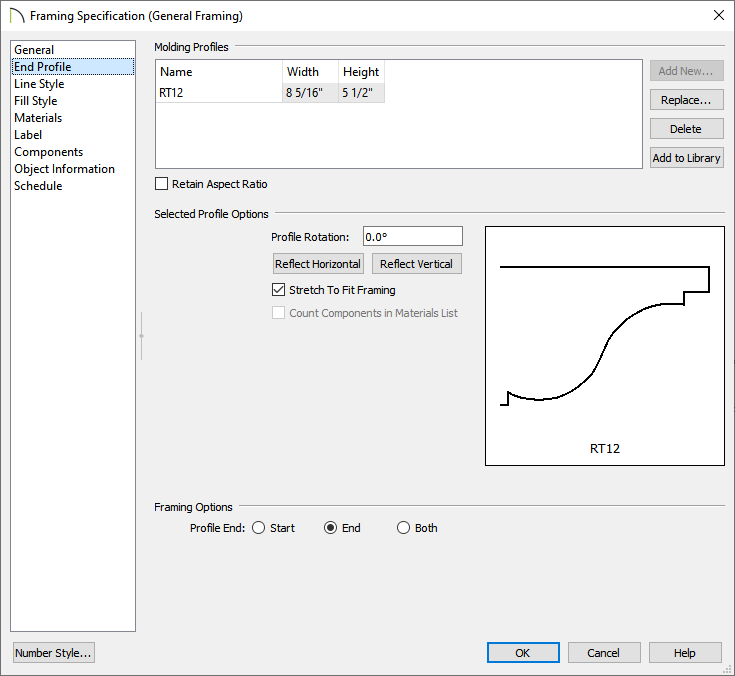
- Select the Add New button, then browse the Library for an appropriate decorative end profile to apply.
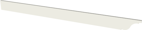
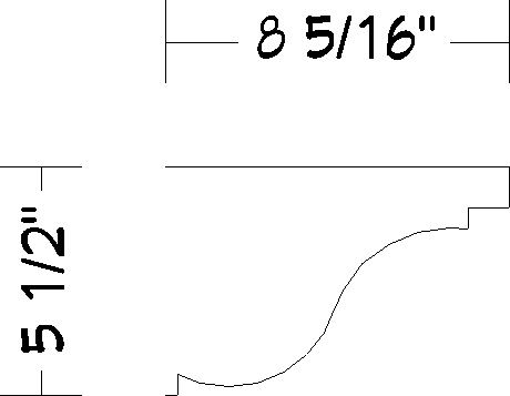
In this example, we have chosen the RT12 profile, which can be found by navigating to Chief Architect Core Catalogs> Architectural> Moldings, Profiles, Extrusions> Rafter Tails.
You can also create your own profiles to be used. For more information, please see the "Creating and Editing Molding Profiles" resource in the Related Articles section below.
- Once a profile has been chosen, click OK.
- By default, the Stretch to Fit Framing box will be checked, disabling the ability to adjust the Width and Height fields for the chosen profile. If you'd like to adjust these properties, uncheck this setting.
- You can choose to rotate or reflect the profile here as well.
- At the bottom, choose which end of the framing member you would like the decorative end to be applied to: Start, End, or Both.
- On the Materials panel, choose your desired material for the framing member, then click OK to close the dialog and confirm the changes.
- Take a Camera
 view to see the results.
Creating a framing member with a decorative end in X12 and prior versions
- Create a New Plan
 , navigate to 3D> Create Orthographic View> Cross Section/Elevation
  view, then click and drag in an area of your plan to create a section view.

- In the section view, use the various CAD tools, such as Draw Line
 and Draw Arc
  , to define the decorative end to your liking. It's important that the height of the decorative end is appropriately sized for the framing member that it will be applied to, and that the lines and arcs that make up the decorative end are connected at their end points to form a single CAD polyline object.
You can also use the existing profiles that are located in the Library Browser  under Chief Architect Core Catalogs> Architectural> Moldings, Profiles, Extrusions for this process. If you choose a profile from the library, right-click on it, select Place Molding Profile from the contextual menu, then click in the section view to place a CAD polyline of the profile.
In this example, the RT12 profile located in the Rafter Tails subfolder is used.
- If further adjustments need to be made to the CAD polyline, use the various edit handles and edit tools when an edge is selected.
- Use the Break Line
 edit tool to add breaks or corners to a polyline's edges.
- Use the Change Line/Arc
 edit tool to change a selected edge from a straight line into an arc, or vice versa.
- If you would like to maintain the same shape and proportions, but increase the overall size, you can do so using the Concentric
 edit behavior found by navigating to Edit> Edit Behaviors
  . Once the size is to your liking, make sure to switch back to the Default
  edit behavior.
- When the profile is defined to your liking, select the top horizontal edge of the profile, then click on the Open Object edit tool.
- On the Selected Line panel of the Polyline Specification dialog that displays:
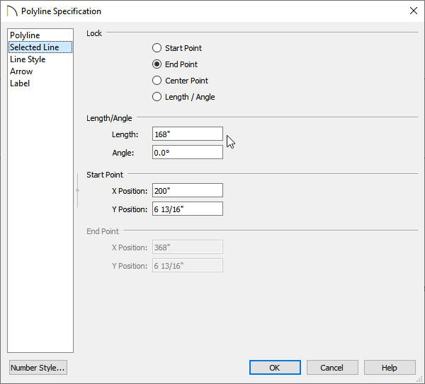
- Select the End Point radio button under the Lock section.
- Enter an appropriate Length for the top edge of the beam or joist.
In this example, 168" (14') is specified.
- Click OK.
- Select Window> Fill Window
 to see the results so far.

- Using the Draw Line tool, draw a horizontal line starting from the bottom of the profile until the end point aligns with the the top edge, then draw a vertical line connecting them together.

- You can confirm that a polyline is closed by opening its specification dialog and accessing the Polyline panel. Here, you can check to see if an Area value is provided or if the words "Not closed" are present.
- If you'd like the decorative end to be on both sides of the framing member, utilize the Copy/Paste
 and Reflect About Object
  edit tools. Please see the "Using the Reflect About Object Tool" resource in the Related Articles section below for more information.
- This polyline represents the framing member, so ensure that both the shape and the size are accurate before proceeding to the next step.
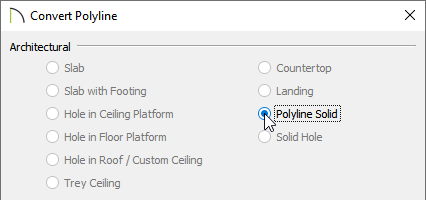
- Select the closed polyline, then click the Convert Polyline
 edit tool.
- In the Convert Polyline dialog that displays, select the Polyline Solid option, then click OK.
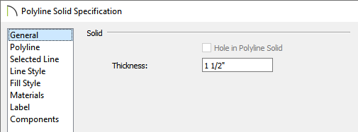
- In the Polyline Solid Specification dialog, which opens next, specify the desired Thickness on the General panel, choose an appropriate material on the Materials panel, then click OK.
- Select the polyline solid in the cross section/elevation view, then click on the Convert Selected to Symbol
 or navigate to Tools> Symbol> Convert to Symbol
  from the menu.
- In the Convert To Symbol dialog that displays:
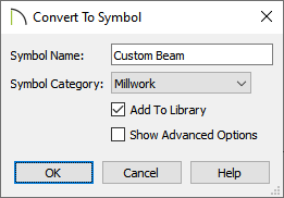
- Specify the Symbol Name for the framing member. In this example, "Custom Beam" is specified.
- Select a Symbol Category from the drop-down menu. In this example, the "Millwork" category is chosen, but "Geometric Shapes" would also be an appropriate choice in this scenario.
- Ensure that the Add To Library box is checked to save the new symbol in the library.
- Click OK.
- Your custom framing beam or joist will now be located in the User Catalog section of the Library Browser .
The newly created framing symbol is now ready to be used in a custom building application, such as a pergola.