QUESTION
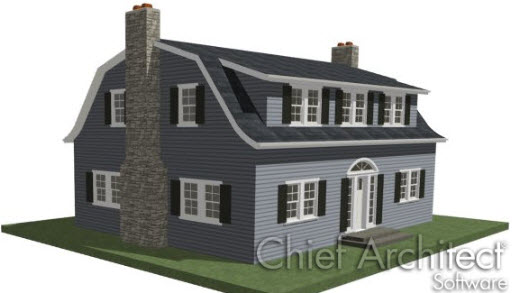
I am designing a Dutch Colonial gambrel roof with dormers. I can't use the Dormer Tools because the roof has more than one pitch, so what do I need to do?
ANSWER
One of the components of an automatic dormer is a Roof Hole, which by definition must always be placed in a single roof plane. When a dormer needs to span more than one roof plane, as it does in a gambrel roof, it must be drawn manually.
In this example, a shed dormer will be added to a gambrel roof with a Dutch kick, or flared eaves. To learn how to create this type of roof, see article KB-00875: Creating Curved or Flared eaves linked in the Related Articles section at the bottom of this article.
To draw the dormer walls
- Open the plan in which you would like to add a dormer to a roof with multiple pitches.
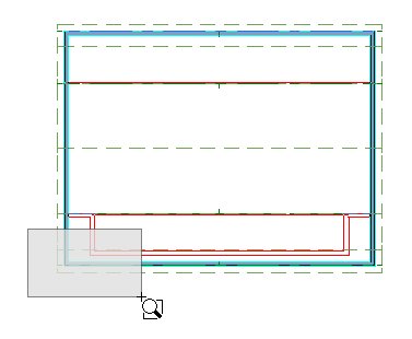
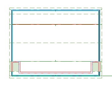
- In this example, a 30' x 40' single story structure with a roof with three different pitches is used.
- Select Build> Floor> Build New Floor
 from the menu, and create a 2nd floor based on the first floor plan.
- In the New Floor dialog, make sure that Move the roof over the highest floor up is unchecked.
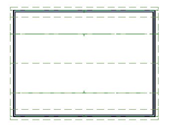
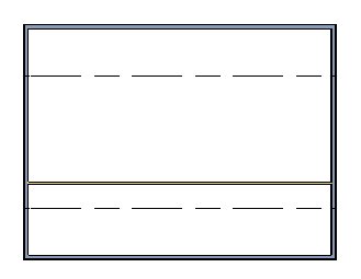
- On the new Floor 2, notice the dashed lines that run parallel to the roof ridge. These are ceiling break lines, which represent the division between the flat, full-height ceiling and the angled, lower ceiling under the roof.
- Select Build> Wall> Straight Interior Wall
 from the menu, then click and drag to draw an interior wall parallel to the ceiling break lines.
- Do not try to position it accurately as you draw - it can be moved into position precisely in a moment.
Knee walls typically have unused attic space on one side. If you want, you can create a custom wall type with only one sheetrock layer.
- Click on the newly drawn wall to select it, then click the Open Object
 edit button to display the Wall Specification dialog.
- On the Roof panel, check the box beside Knee Wall, then click OK.
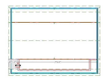
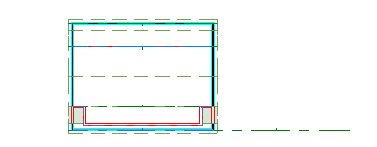
- With the wall still selected, click on a dimension line that tells you how far it is away from the exterior wall over which you would like to design a dormer.
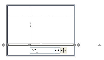
- In the inline text field, type the desired distance that you would like this wall to be from the exterior wall, then press Enter on your keyboard.
- In this example, a value of 72" (6') is used so that the wall is located at the ceiling break.
- If you do not see a temporary dimension when you click on the wall, select View> Temporary Dimensions
 from the menu to enable this feature.
- Select Build> Wall> Straight Exterior Wall
 from the menu, then click and drag to draw the front and two side walls of the dormer.
- Draw the walls sequentially in a clockwise direction to make sure that the siding material displays on the outside of the structure.
- Use dimensions to accurately position the dormer walls relative to the larger structure.
- In this example, the side walls are 3 feet away from the exterior side walls and the front wall is 1 foot from the front exterior wall.
- Click the Select Objects
 button, then click in the room formed by the knee wall, dormer walls, and exterior walls to select it and click the Open Object edit button to display the Room Specification dialog.
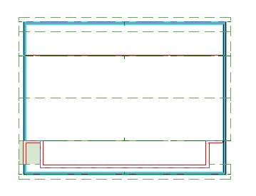
- On the General panel, select "Attic" from the Room Type drop-down list, then click OK.
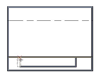
- Select Build> Wall> Break Wall
 from the menu, then click at the intersection of the knee wall and each of the dormer side walls.

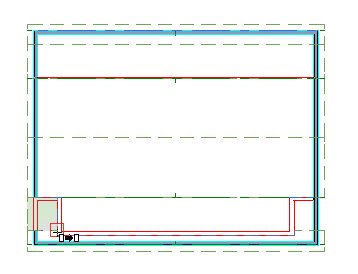
Click the Select Objects button, then click on the middle section of knee wall and Delete  it.
it.
- If you want dormers on both sides of the structure, repeat steps 4 through 12 on the other side of the model.
The dormer walls are now in place, but the roof above them prevents them from extending upward. You can now edit the roof planes so that they accommodate the dormer.
To notch the lower roof around the dormer
- Go Down One Floor
 to Floor 1 and select Tools> Floor/Reference Display> Reference Display
  from the menu to turn on the Reference Display.
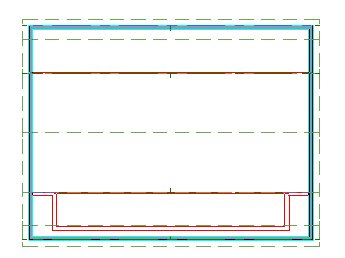
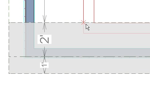
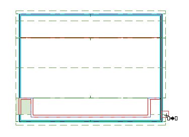
- The walls on Floor 2 will now display in red on Floor 1.
-
Zoom
 in on one of the front corners of the dormer so that you can clearly see both the red lines that represent the dormer walls and the roof plane edges distinctly.
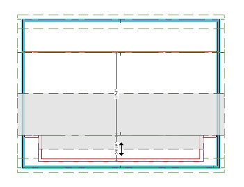
- Click the Select Objects button, then click on the roof eave closest to the dormer walls to select it.
- Click the Break
 edit button, then position your cursor over the back edge of the roof plane, near the outside edge of the dormer side wall.
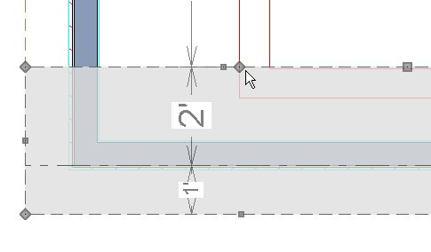
- When your pointer is over the intersection of the two, a red, square Endpoint Snap Indicator
 will display at the intersection.
- If you do not see this Snap Indicator, make sure that Object Snaps
 - and particularly, Endpoint Snaps
  - are enabled.
- When the Endpoint Snap Indicator can be seen, click once to place a break, or corner, at that location.
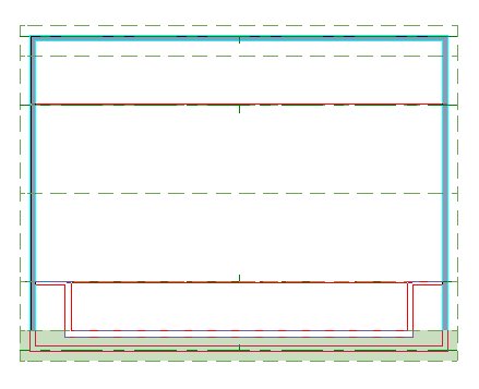
- Repeat steps 3 through 5 on the other side of the dormer.
- With the eave roof plane still selected, Zoom Out
 as needed, select the new edge created between the two breaks that you added and drag it towards the outside of the dormer front wall.
- When the roof edge is over the outside of the dormer wall, the On Object Snap Indicator
 will display.
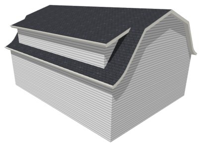
- In the image above, the eave roof plane is shown with a green fill to better illustrate its final shape.
To divide the middle roof plane in two
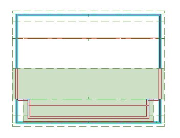
- Click on the middle roof plane to select it, then use its edit handles to pull one side back so that it no longer covers the dormer.
- When the roof plane edge reaches the outside of the dormer side wall, the On Object Snap Indicator will display. Release the mouse button to snap the roof plane edge to the outside of the dormer wall.
- In the image above, the resulting roof plane is shown with a green fill to better illustrate its size and shape.
- With the roof plane still selected, click the Copy/Paste
 edit button.
- With the roof plane still selected, click the Point to Point Move
 edit button.
- Move the mouse pointer over the bottom right corner of the roof plane. When you see the Endpoint Snap Indicator , click once.
- Move the pointer over the top right corner of the lower eave roof plane. As before, when you see the Endpoint Snap Indicator , click once.
- A copy of the selected roof plane will be placed so that its bottom outside corner is aligned with the top outside corner of the roof plane below it.
- When the copy is created, notice the green dashed line extending to the right: this is the new roof plane's baseline.
- The original roof plane has a similar baseline, but it is hard to see because it is colinear with the ridge edge of the eave roof plane.
-
Zoom Out as needed so you can see the entire baseline.
- Click the Select Objects button, then click on the baseline and use its edit handles to resize it so that it is contained within the new roof plane.
To extend the upper roof plane over the dormer
- Click on the upper roof plane to select it, then click the Break edit button and select sticky mode
 .
.
- Position your cursor over the front edge of the roof plane, outside one of the dormer side walls and click once at that location and once on the other side of the dormer.
- With the eave roof plane still selected, select the new edge created between the two breaks that you added and drag it past the outside of the dormer front wall.
- Select and drag each of the roof plane edges that run parallel to the dormer side walls as needed to produce the desired overhangs.
- In the above image, the roof plane is shown with a green fill to better illustrate its final shape.
You can also move the roof plane edges precisely using dimensions.
- Create a Full Overview
 to see the results.