QUESTION
I need to create a basic table of text notes contained in a grid, such as for a legend. How can I accomplish this in Chief Architect?
ANSWER
There are a number of ways to approximate the look of tables in Chief Architect, including using the CAD tools to create boxes, lines, and Rich Text. In this article, however, we will discuss creating a basic table using the Text tool.
To create a table using the Text tool
- From the menu, select CAD> Text> Text
 , then click in plan to open the Text Specification dialog.
Please note you cannot create a simple table using Rich Text.
- On the Text panel, create the text you want displayed in your table, and use the Tab key on your keyboard to pan between text that you want to be separated in to different columns.
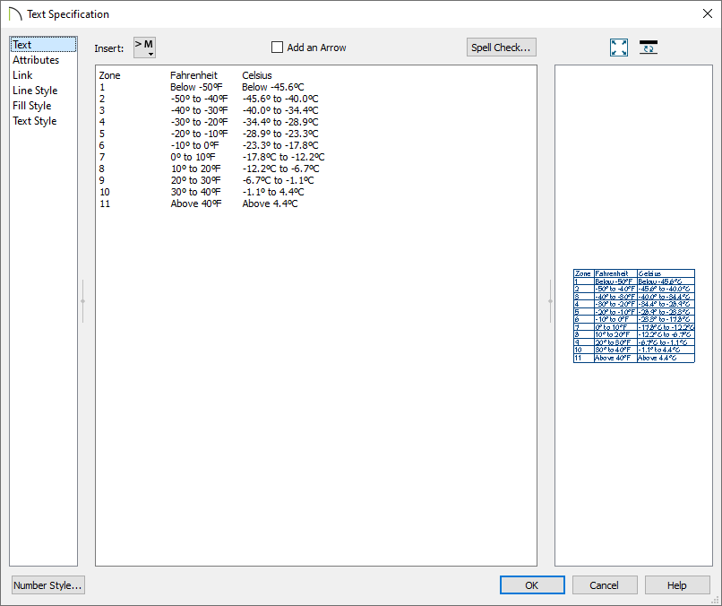
- On the Attributes panel:
-
Place a check next to Display Border.
-
Place a check next to Display Grid Lines.
-
Use the drop-down menu to select an Alignment, such as Centered.
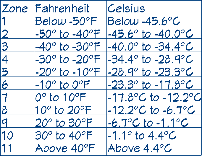
- On the Line Style panel, you can change the Line Color of the grid to a different color, if desired.
- Make any other desired changes in this dialog, then click OK to finish creating the table.
- Starting in X13, individual text objects can be added to the library using the Add to Library
 edit button.
In X12 and prior versions, the text box will need to be part of a CAD block before it can be added to the library. To do this, create a selection marquee encompassing the text box, click the Make CAD Block  edit button, then click the Add to Library edit button.
If you are creating a custom legend key, or want to modify a legend that exists in the library, such as the Electrical Legend or Plumbing Symbols, then you will likely also want to place CAD blocks representing the 3D objects.
To add CAD blocks
- Select CAD> CAD Block Management
 .
.
- Navigate to the CAD block's name in the list, click on it to highlight it, then select the Insert button.
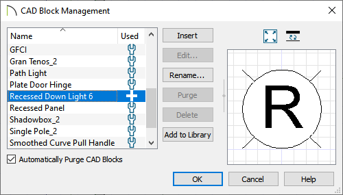
- Click in the plan where you want to place the 2D CAD block.
- In X13 and newer versions, if you want to make changes to a individual elements of a CAD block, select the Edit CAD Block
 edit button to open a separate window. Notice that the CAD block is no longer a single, non-editable unit. Instead, you will be able to select and modify each individual CAD line, polyline, and text object.
In X12 and prior versions, click the Explode CAD Block  edit button instead. Do note that a separate window will not open when selecting this tool.
It is possible to nest a CAD block within another CAD block. If, after clicking Edit CAD Block or Explode CAD Block tool, you find an object that you cannot edit as expected, click on it to select and then check the Edit toolbar for the Explode CAD Block edit button. If you find this button, click on it and continue editing.
- When your CAD block is edited to suit your needs, select Tools> Active View> Save Active View
 in X13 and newer versions. You may be prompted with a Question dialog asking if you'd like to replace all instances of the block with the copy you have modified. Choose your desired option to proceed.
In X12 and prior versions, create a selection marquee using the Select Objects  tool, then use the Make CAD Block edit button to block it back together.
- Your modified CAD block can also be added to your library for future use; click on the CAD block to select it, then click the Add to Library edit button.