QUESTION
I would like to design a solarium. How can I do this?

ANSWER
There are various approaches to designing a solarium, greenhouse, or sunroom. As this article explains, you can create a solarium using metal framing, windows, and skylights.
To create and use a solarium wall type
-
Select Build> Wall> Define Wall Types
 from the menu.
- In the Wall Type Definitions dialog, click the New button to create a new wall type.
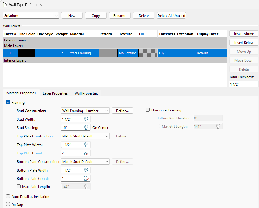
- Give your new wall type a short, descriptive, unique name so that it can be easily identified later.
- Specify the desired Thickness of your steel wall.
For the purposes of this example, a Thickness of 1 1/2" is specified.
- Click the Material column to the right of layer 1, browse to Core Catalogs> Materials> Framing, select the Steel Framing material for your walls, then click OK.
- Make any changes you would like to the Line Style or Fill Style, but bear in mind that your steel wall will be thin, so these changes may not be visible when you are zoomed out.
- On the Material Properties tab, check the box for Framing and then set your Stud Width, Stud Spacing, and Top/Bottom Plates to your specifications.
- Click OK to close the dialog and apply your changes. The new steel wall type is now available to replace existing walls in your plan.
- Using the Select Objects
 tool, select an existing wall you'd like to change the a solarium wall and use the Open Object
  edit tool to open the Wall Specification.
- On the Wall Types panel, select the newly created type from the Wall Type drop-down list and click OK.
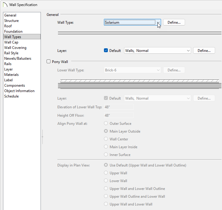
- Repeat this process on any other walls that will be the walls for the solarium.

- Using the Select Objects tool, select the solarium room and use the Open Object edit tool to open the Room Specification.
- On the General panel set the Room Name to Solarium
- On the Structure panel set the Rough Ceiling height for your solarium.
- Uncheck the Flat Ceiling Over This Room to make the room have a vaulted space.
- Make any other desired changes and click OK.
Before building the roof planes, we'll adjust our roof settings in the Build Roof  dialog.
To create a solarium roof system
- Go to Build> Roof> Build Roof to open the Build Roof Specification.
- On the Roof panel, the Pitch is set to 8" and the Eave and Roof overhang are both set to 1/2".
- On the Options panel, the Eaves are set to be Square cut.
- On the Structure panel, in the Roof Layers section click Edit for your Surface to open the Roof Surface Definition dialog.
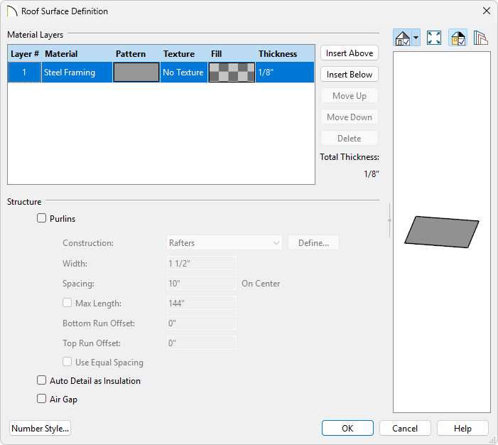
- Select the OSB-Hrz layer and click Delete.
- Click on the name of your roofing material to open the Select Material dialog.
- Go to Core Catalogs> Materials> Framing and Structural, select the Steel Framing material, and click OK.
- Set your desired Thickness. In this example we will use 1/8".
- Click OK.
- Remaining on the Structure panel, in the Roof Layers section click Edit for your Structure to open the Roof Structure Definition dialog.
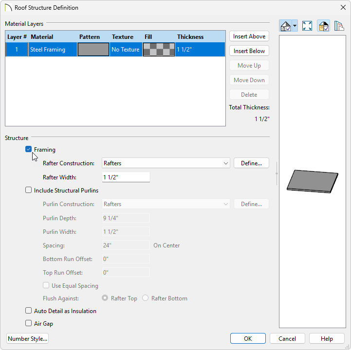
- Select the Fir Framing material to open the Select Material dialog.
- Go to Core Catalogs> Materials> Framing and Structural, select the Steel Framing material, and click OK.
- Set your desired Thickness. In this example we will use 1 1/2".
- Click OK.
- Remaining on the Structure panel, in the Roof Layers section click Edit for your Ceiling to open the Roof Ceiling Finish Definition dialog.
- Select and Delete the ceiling finish layers.
- Click OK.
- Underneath of the Roof Size section:
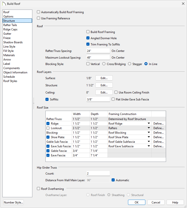
- Uncheck the Lookout checkbox
- Excluding the Width of the Gable and Eave Fascias, set all the Roof Size measurements to 1 1/2" to match the wall structure.
- Make any other desired changes to the roof such as adding/removing Ridge Caps and Gutters and click OK.
- Now that the roof settings are adjusted, the roof can be generated using the Build Roof dialog or by building it manually using the Roof Plane
 tool. In this example, a gable roof was generated by using the Build Roof dialog.

For more information on creating different roof styles automatically, please see the Related Articles section below.
To add skylights to a solarium roof
With the roof placed over the solarium room, skylights can now be added to create the finished glass solarium roof. We'll make use of Multiple Copy and the Reflect About Object edit tools option to replicate a skylight and duplicate them across the roof.
- Select Edit> Default Settings
 and in the Default Settings dialog select Skylight* and click Edit to open the Skylight Defaults dialog.
- In the Skylight Defaults:
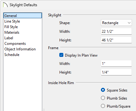
- Specify the Shape you'd like new skylights to be.
In this example we will use the Rectangle shape.
- Adjust the Width and Height that new skylights will come in as.
- Adjust the Width and Height of the skylight frame.
In this example we will set the Width to 1" and the Height to 1/4".
- Click OK and Done to save your changes.
- Select Build> Roof> Skylight
 from the menu and place a skylight.
- Select the skylight, select the Multiple Copy
 edit tool, and then select the Multiple Copy Interval
  edit tool to open the Multiple Copy dialog.
- In the Multiple Copy dialog set the General Objects Primary Offset to how far you'd like your skylights to be spaced, accounting for the width of the skylight, and click OK.
In this example we will set it to 25 1/2", which will give us a 3" spacing between skylights.
- Select the edit handle in the center of the skylight and then click and drag to create multiple copies of your skylight, spaced 3" apart.

- Select the skylights in the roof plane and use the Copy/Paste
 edit tool, then use the Reflect About Object
  edit tool to copy the design over to the neighboring roof plane.

Objects can be group selected by holding the Ctrl or Command key and left clicking on objects us creating a selection marquee. For more information on group selecting objects, see the Related Articles section below.
To change a roof plane to glass
If you need to have a continuous stretch of glass on the above roof plane, you can change the material of the roof plane itself to glass.
- Select your Roof Plane and use the Open Object edit tool to open the Roof Plane Specification.
- On the Structure panel, in the Roof Layers section click Edit for your Surface to open the Roof Surface Definition dialog.
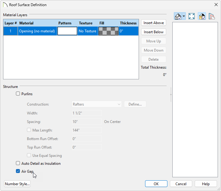
- Select the material layers and click Delete until there is only a single layer.
- Click on the name of the material to open the Select Material dialog.
- Go to Core Catalogs> Materials> Insulation, select the Opening (no material) material, and click OK.
- Set the Thickness to 0".
- Check the Air Gap checkbox to prevent the layer from being displayed in 3D views, or included in Material Lists.

- Click OK.
- Remaining on the Structure panel, in the Roof Layers section click Edit for your Structure to open the Roof Structure Definition dialog.
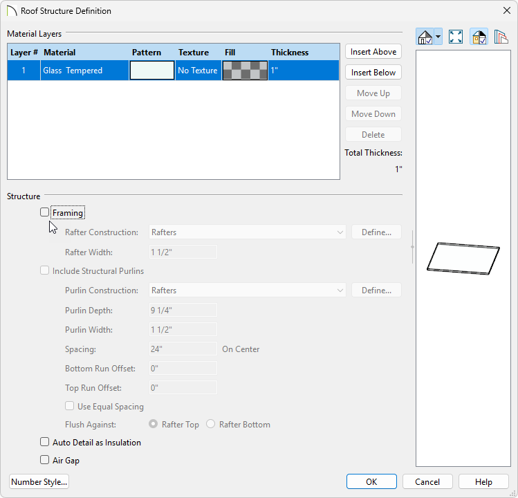
- Select the Fir Framing material to open the Select Material dialog.
- Go to Core Catalogs> Materials> Glass and Glazing, select your glass material, and click OK.
- Set your desired glass plane Thickness. In this example we will use 1".
- Uncheck the Framing checkbox.
- Click OK.
To add glass to solarium walls
With the steel walls and roof in place, it's time to place windows in the steel walls to create our glass solarium walls. We'll follow a process similar to the previous steps replicating the skylights.
- Select 3D> Create Orthographic View> Cross Section/Elevation
 to create an exterior elevation of either the north or south wall of the solarium.
- Select Build> Window> Window
 to place a window in the solarium wall and make any necessary modifications. For this example, the following settings are used:
- On the Casing panel, the Interior and Exterior Casing are removed.
- On the Lintel panel, the Interior and Exterior Lintel are removed.
- On the Sill panel, the Interior and Exterior Sill are removed.
- On the Sash panel, the Sash is removed.
- On the Frame panel:
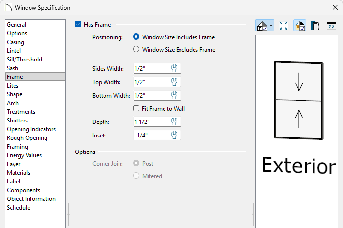
-
Sides, Top, and Bottom Width are set to 1/2".
-
Fit Frame to Wall is unchecked.
- The Depth is set to 1 1/2" and the Inset is set to -1/4".
- On the Framing panel, the Rough Opening values for Each Side, Top, and Bottom are all 0".
- On the Materials panel, all components of the Window are using the Steel Framing material, apart from the Glass.
- Select the window placed in the solarium wall and use the Multiple Copy edit button to replicate the window across the wall at your desired interval.
- Group select the windows by navigating to Build> Window> Window from the menu, hold down the Shift key on the keyboard, and using the left mouse button, click and drag a selection marquee. With the windows selected, use the Copy/Paste edit button to create copies and paste them on the adjacent walls.


