QUESTION
I would like to change the colors used in plan view for a variety of objects - for example, cabinets, doors, electrical items and dimension lines. How do I do this?

ANSWER
In Chief Architect, you can change both the line color and the line style used to represent nearly all objects in floor plan view - including walls, floors, furniture and many other objects. Line color and style can be changed for an entire category of objects, organized by layer in the program, or for individual objects.
To change the display of a layer
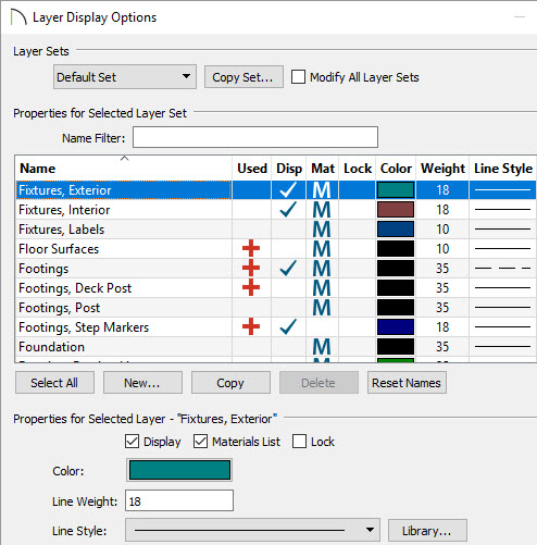
- Select Tools> Layer Settings> Display Options
 from the menu.
- In the Layer Display Options dialog:

- Click on a layer to select it.
- In the Properties for Selected Layer section at the bottom of the dialog, select the desired Color and Style for the lines representing all objects on this layer.
- If you would like your changes to affect all layer sets, check the box beside Modify All Layer Sets at the top of the dialog.
- Click OK to close the dialog and apply your changes.
The Modify All Layer Sets options is a state, rather than an action, which means that it will remain checked until you uncheck it again, or until you close the Layer Display Options Dialog box.
To change the display of a single object
- With the Select Objects
 tool active, click on an object that you would like to modify the 2D display of to select it.
- Click the Open Object
 edit button to open the object's specification dialog.
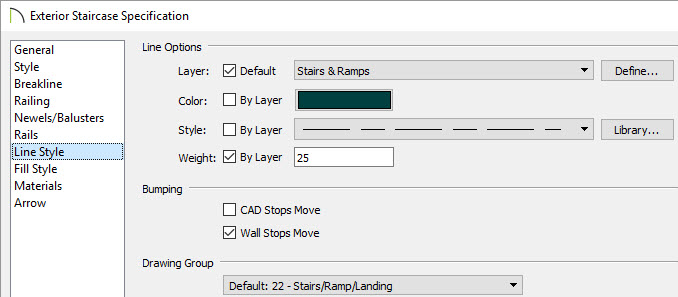
- On the Line Style panel of the specification dialog:

- Click the color bar and select the desired Color for your line in the Color Chooser dialog.
- Select a Line Style from the Style drop-down list.
- Select a Line Weight which will display when Show Line Weights
 is turned on as well as when printed.
- Also, the drawing order of the object that's open can be changed if it becomes superimposed with other objects. This can be done using the Drawing Group drop down.
- Some objects, such as walls, doors, and windows do not have a Line Style panel. Instead, you can place individual objects on any layer that you need to on the Layer panel of the specification dialog.
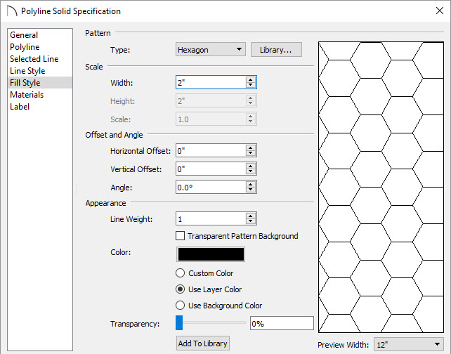
- A number of objects also have a Fill Style panel in both their defaults and specification dialogs.

- Select a Fill Pattern from the Type drop-down list.
- Specify the pattern's Scale options to your liking.
- Specify the Offset and Angle settings.
- Use the Appearance settings to choose a Color for the pattern lines and specify Transparent Pattern Background if desired.
- The Transparency of the pattern lines can also be adjusted.

 from the menu.
 tool active, click on an object that you would like to modify the 2D display of to select it.
 edit button to open the object's specification dialog.
 is turned on as well as when printed.