QUESTION
I want to change the 2D display of a symbol from the library such as an electrical switch or built-in appliance. How can I do this?
ANSWER
Architectural objects in the library are represented in floor plan view by 2D CAD blocks. In some cases, you may want to change something about the 2D display of a symbol. The process for doing so will depend on which version of Chief Architect you're using.
To edit the 2D display of a symbol in X13 and newer versions
- In the Library Browser
 , browse for and select the symbol you would like to use, then click to place it in your plan.
For the purposes of this example, we will browse to Mechanical, Electrical, Plumbing> Electrical> Switches> Garbage Disposal Switch.
- Using the Select Objects
 tool, click on the newly placed symbol, then click on the Edit CAD Block
  edit button.
You can also navigate to CAD> CAD Block Management from the menu, select the name of the 2D CAD block that you would like to edit, then click the Edit button.
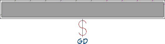
- In the CAD Block window that displays next, the 2D CAD block will be exploded into individual objects, allowing for modifications to be made.
- Select the "GD" text and click the Open Object
 edit button.
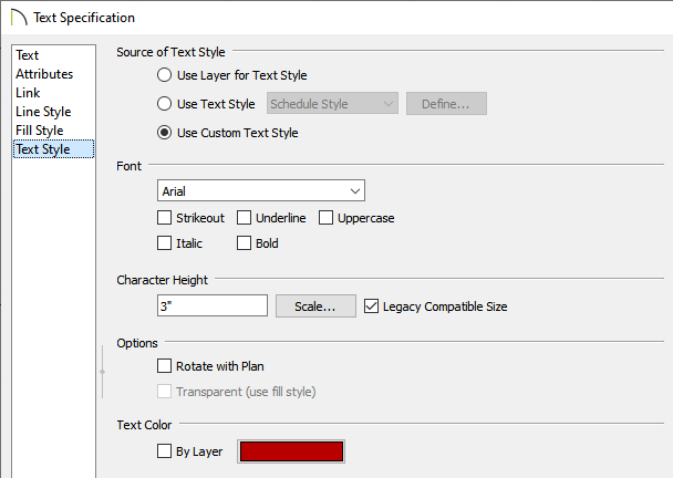
- In the Text Specification dialog that displays, you can modify the text you would like to see on the Text panel. The Font, Character Height, Text Color, and other attributes can be changed on the Text Style panel.
For the purposes of this example, we will choose the Use Custom Text Style option, change the Font to Arial, set the Character Height to 3", uncheck the "By Layer" box for the Text Color, then specify a red color for the text.
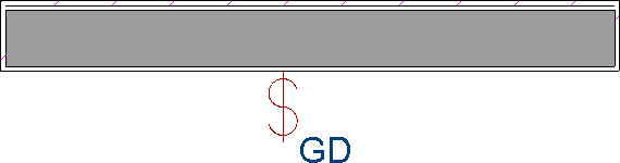
- Make any additional adjustments, such as to the position of the text, then click OK

- Make any other desired changes to the other CAD objects, then click Tools> Active View> Save Active View
 .
.
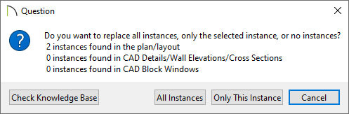
- In the Question dialog that appears, you can choose to replace instances of the existing CAD block with the newly modified version. Choose an appropriate option to proceed.
- Close out of the CAD Block window to return back to your plan.
- You can now add the symbol with its customized 2D block to your User Catalog folder in the Library Browser by selecting the symbol and clicking the Add to Library
 edit tool.
To edit the 2D display of a symbol in X12 and prior versions
- In the Library Browser , browse for and select the symbol you would like to use, then click to place it in your plan.
For the purposes of this example, we will browse to Mechanical, Electrical, Plumbing> Electrical> Switches> Garbage Disposal Switch.
- Select CAD> CAD Block Management
 from the menu, and in the list of CAD blocks, find the Garbage Disposal CAD block and select it.
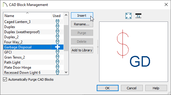
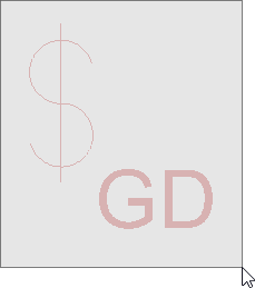
- With the CAD block selected, click the Insert button, then click somewhere in the drawing area to place a copy of the selected CAD block.
As the CAD block will be placed on the Default CAD layer, its line color may be different than it appears when it is applied to a library symbol.
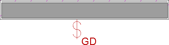
- For the purposes of this example, we will enlarge the "GD" text, as well as change its color.
- To edit the content of the CAD Block, begin by selecting it and clicking the Explode CAD Block
 edit button.
- Next, select the "GD" text and click the Open Object edit button.
- In the Text Specification dialog that displays, you can modify the text you would like to see on the Text panel, as well as adjust the Font, Character Height, Text Color, and other attributes on the Text Style panel.
For the purposes of this example, we will set the Character Height to 3", uncheck the "By Layer" box for the Text Color, then specify a red color.
- Once the text is to your liking, click OK.
- Using the Select Objects tool, left-click and drag a marquee around the objects.
- With the objects selected, click the Make CAD Block
 edit button to block the objects back together.
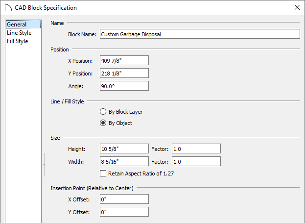
- Select the block and click the Open Object edit button.
- On the General panel of the CAD Block Specification dialog that displays, type a short, descriptive name for the CAD block, then click OK.
In this example, we will name the CAD Block "Custom Garbage Disposal".
- To use this newly created CAD block for the electrical symbol, select the Garbage Disposal Switch symbol you placed in your plan in Step 1, then click the Open Symbol
 edit button.
- On the 2D Block panel of the Symbol Specification dialog, select the block created in the previous step from the list of Available CAD Blocks, then click OK.
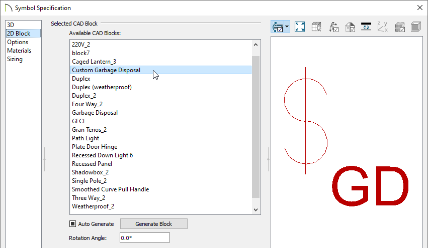
CAD blocks that have nested blocks within them cannot be assigned to 3D objects or to images.
- The symbol will now display the CAD block you created as its 2D symbol.
- You can now add the symbol with its customized 2D block to your User Catalog folder in the Library Browser by selecting the symbol and clicking the Add to Library edit tool.