QUESTION
I would like to add panels to the sides and back of a base cabinet. How can I do this?

ANSWER
Additional panels can be added to the side and back of cabinets from within a cabinet's specification dialog, or manually, by placing panels from the library directly into the plan.
To add or customize side or back panels
- Using the Select Objects
 tool, select the base cabinet you wish to customize and click the Open Object
  edit button to open the Base Cabinet Specification dialog.
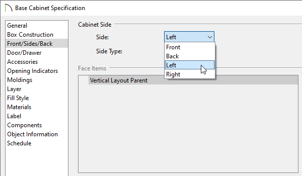
- On the Front/Sides/Back panel, use the Side drop-down menu and choose which side of the cabinet you wish to modify.
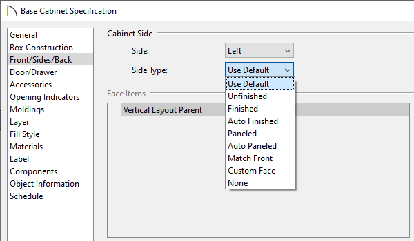
- Use the Side Type drop-down menu to choose the type desired.
-
Use Default - uses the default configuration as specified in the Cabinet Defaults dialog.
-
Finished / Unfinished - leaves the selected side blank; displays Finished or Unfinished in Cabinet Schedules.
-
Auto Finished - sets the selected side to Finished or automatically sets it to Unfinished when adjacent to another cabinet or a wall.
-
Paneled - applies the default panel as specified on the Accessories dialog panel, to the selected side.
-
Auto Paneled - applies the default panel to the selected side only when it is not adjacent to another cabinet or a wall.
-
Match Front - applies the same face items as the cabinet front to the selected side.
-
Custom Face - enables the Face Items settings, allowing for full customization of the selected side.
-
None - removes the side of the cabinet box completely.
This option is not available in legacy versions.
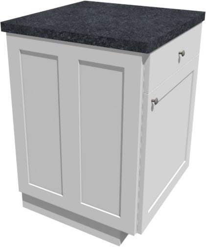
- In this example, set the Side Type to Custom Face, and customize it accordingly:
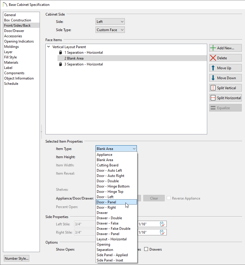
- Under the Face Items section, select the Blank Area.
- Under the Item Type drop-down, select Door - Panel.
- Under the Face Items section, with the Door - Panel selected, click the Split Vertical
 button to create a split side panel.
- Click OK to accept the changes and close the dialog.
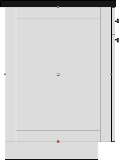
- Take a Camera
 view to see the results.
In some situations it may be necessary to manually place cabinet panels.
To manually place panels
- If the Library Browser is not already open, navigate to View> Library Browser
 while in a floor plan view.
- Browse to a library containing cabinet panels, such as Chief Architect Core Catalogs> Architectural> Cabinet Doors, Drawers, & Panels, or a manufacturer catalog.
- Select a panel/door, then click to place it into a blank area of the plan, making sure not to click onto a cabinet.
A Question message may appear stating "No suitable cabinet was selected to insert the library cabinet door/drawer. Would you like to place the door into the plan as a fixture?" Click Yes and the panel will appear as an independent object in the plan.

- Use the Select Objects tool to select the panel and click the Open Object edit button to open the Fixture Specification dialog:
- On the General panel, specify the Width, Height, Depth, and Elevation of the panel.
- On the Label panel, check Suppress Label if you'd like to hide the label.
- Click OK to confirm the changes and close the dialog.
- Select the panel object, rotate it if necessary, then move it so that it snaps to the side of the cabinet.
- Navigate to 3D> Create Orthographic View> Cross/Section Elevation
 , then click and drag a camera looking at the panel object.
- In the elevation view, use the Select Objects tool to select the panel and use the edit handles to manually reshape it, or click Open Object to manually enter the proper dimensions for the panel.