QUESTION
I would like to create a custom in-ground swimming pool. How do I do this?
ANSWER
Using the terrain features, 3D/polyline solids, and molding polylines, you can create a custom in-ground swimming pool.
To create a hole for the pool
- Select Terrain> Create Terrain Perimeter
 from the menu to create terrain in which the pool can be designed. You can skip this step if you have a terrain perimeter already drawn.
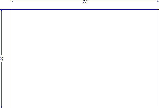
- Select Terrain> Feature> Rectangular Feature
 from the menu, then click and drag to draw a rectangular feature polyline contained inside the terrain perimeter.
In this example, a 20' x 30' rectangular polyline is used, and will form the hole for the swimming pool.
Features follow the contours of your terrain. If you place a feature on a slope, it will follow the slope rather than form a flat area. If your terrain is sloped, use Elevation Lines or a Flat Region to create a level area to place your pool in.
- Select the polyline and click the Open Object
 edit button.
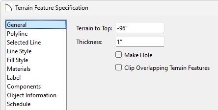
- On the General panel of the Terrain Feature Specification dialog that opens:
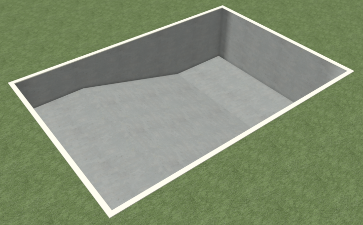
- Change the Terrain to Top to the desired depth of the pool's deepest point.
In X12 and prior versions, change the Height instead.
In this example, -96" is used.
- Click OK to close the dialog and apply your changes.
- Next, select 3D> Create Perspective View> Perspective Full Overview
 to see the results so far.
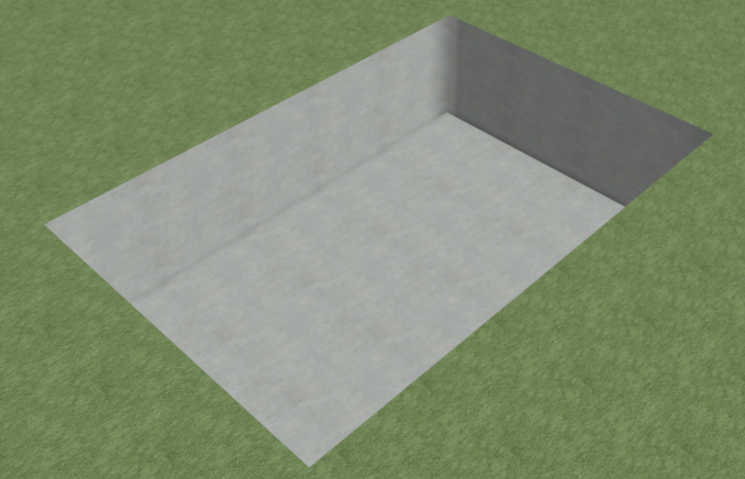
- Once you have verified the camera view, select File> Close View to return to a floor plan view.
To slope the bottom of the pool
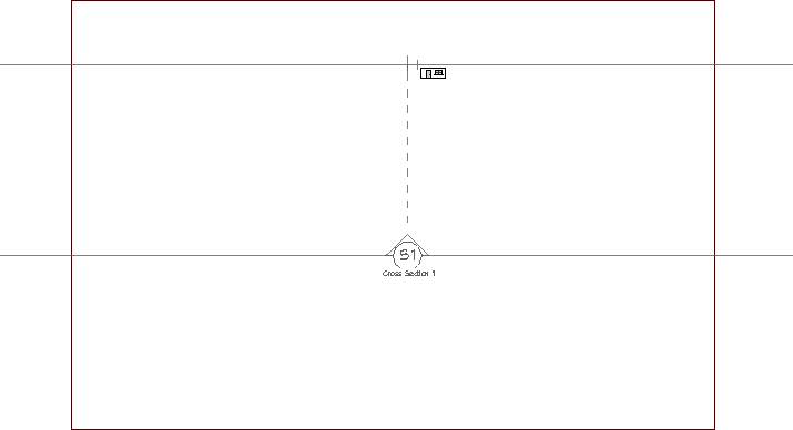
- Select 3D> Create Orthographic View> Back Clipped Cross Section
 , then click and drag a camera arrow that runs perpendicular to the slope that you wish to create.
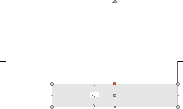
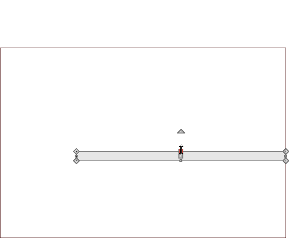
- In the back clipped cross section view, select CAD> Boxes> Rectangular Polyline
 from the menu, then click and drag to draw a rectangle along the bottom part of the pool.
This rectangle will form the shallow end of the pool, as well as the slope to the deep end.
- Click on the top edge of the polyline to select it, then click on the temporary dimension that displays between it and the bottom edge to specify the height above the deep end that you would like the shallow end to be.
In this example, 48" is used.
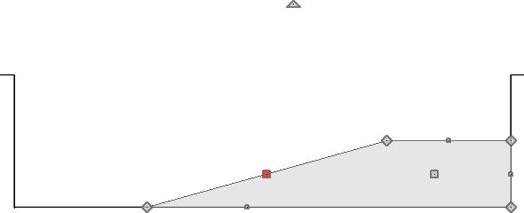
- With the rectangle still selected, click the Add Break
 edit button and click along the top edge of the rectangle to place a break at that location.
- Next, drag the top left corner down to create a slope, as shown in the image below.
- With the rectangular polyline still selected, click the Convert Polyline
 edit button, and in the Convert Polyline dialog that displays, choose the 3D Solid option, then click OK.
In X13 and prior versions, 3D Solids were called Polyline Solids.
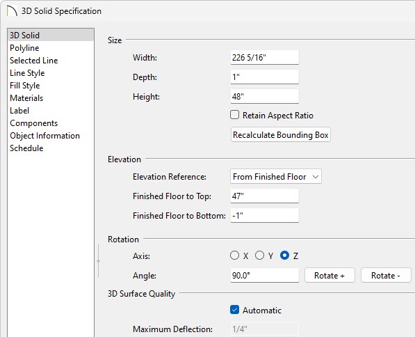
- On the General panel of the 3D/Polyline Solid Specification dialog that opens next, change the Height or Thickness to your desired value, then click OK.
In this example, a value of 48" was used.
- Select File> Close View to close the back clipped cross section view and return to a floor plan view.
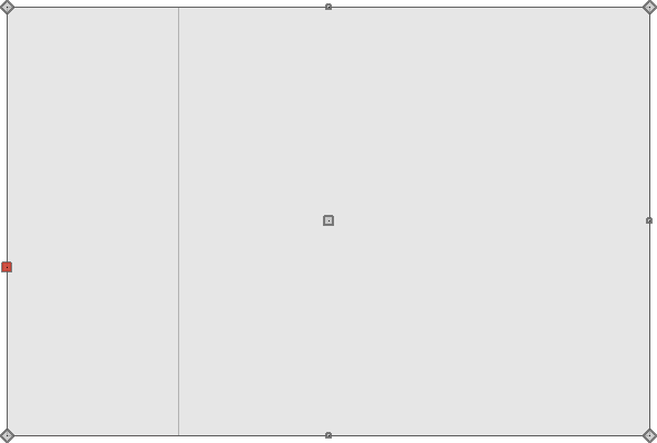
- In a floor plan view, select the newly-created 3D/polyline solid and use the edit handles to adjust its width to match the width of the pool.
To create a rounded ledge around the pool in X16 and newer versions
- Using the Select Objects
 tool, click on the pool feature region to select it, then navigate to Edit> Copy and Paste in Place
  from the menu.
- With the newly created region selected, click the Concentric Resize edit tool.
- With the Concentric Resize
 edit tool selected click the Set Concentric Jump
  edit tool to open the Set Concentric Jump Distance dialog.
- In the Jump Distance box type in your desired ledge distance.
In this example, 3" is used.
- Click OK to close the dialog and apply your changes.
- Place your cursor over one of the diamond shaped edit handles, then click and drag away from the pool. When a second outer polyline displays release the mouse.
- With the newly created feature region still selected, click the Convert Polyline edit button, and in the Convert Polyline dialog that displays, choose the Molding Polyline option, then click OK.
- On the Moldings panel of the Molding Polyline Specification dialog:
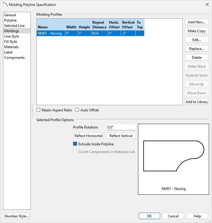
- Click the Add New button, browse to Chief Architect Core Catalogs> Architectural> Moldings, Profiles, Extrusions> Chair Rail, and choose a molding profile.
In this example, NM01-Nosing is used.
- Set the Height, Width, and Offsets to your liking.
In this example, a Width of 6", a Height of 3", and a Vertical Offset of -2" is used.
- Make sure that the box beside Extrude Inside Polyline is selected.
- Make any other desired changes, then click OK.
- Take a Perspective Full Overview to see the results so far.
- Once you have verified the camera view, select File> Close View to return to a floor plan view.
To create a rounded ledge around the pool in X15 and prior versions
- Select Edit> Edit Behaviors
 and click on Concentric , which allows you to resize objects so that the distance moved by each edge is the same.
- Using the Select Objects tool, click on the pool feature region to select it, then navigate to Edit> Copy and Paste in Place from the menu.
- Place the mouse pointer over one of the diamond shaped corner handles.
- Click and drag the handle slowly away from the pool. You will see that it snaps at 1 inch increments.
- Release the mouse button so that a new region is created 3 inches out from the original.
- With the newly created feature region still selected, click the Convert to Plain Polyline
 edit button so that it is no longer a terrain feature.
- Next, with the new plain polyline selected, click the Convert Polyline edit button, and in the Convert Polyline dialog that displays, choose the Molding Polyline option, then click OK.
- On the Moldings panel of the Molding Polyline Specification dialog:
- Click the Add New button, browse to Chief Architect Core Catalogs> Architectural> Moldings, Profiles, Extrusions> Chair Rail, and choose a molding profile.
In this example, NM01-Nosing is used.
- Set the Height, Width, and Offsets to your liking.
In this example, a Width of 6", a Height of 3", and a Vertical Offset of -2" is used.
- Make sure that the box beside Extrude Inside Polyline is selected.
- Make any other desired changes, then click OK.
- Now that we are finished using the concentric edit behavior, select Edit> Edit Behaviors> Default
 to return to the default edit behavior.
- Take a Perspective Full Overview to see the results so far.
- Once you have verified the camera view, select File> Close View to return to a floor plan view.
To add water to the pool
- Select the pool terrain feature created in the first section of this article.
If you initially select an object other the terrain feature, click the Select Next Object  button or press the Tab key on your keyboard.
- With the terrain feature selected, navigate to Edit> Copy/Paste in Place from the menu.
- With the pasted terrain feature still selected, click the Convert Polyline edit button, and in the Convert Polyline dialog, choose 3D Solid, then click OK.
In X15 and prior versions, click on the Convert to Plain Polyline edit button, then click the Convert Polyline edit button, and in the Convert Polyline dialog, choose 3D Solid, then click OK.
- In the 3D/Polyline Solid Specification dialog that displays next:
- On the General panel, set the Height or Elevation to 1", change the Elevation Reference to Absolute, then set the Elevation at Top to -6".
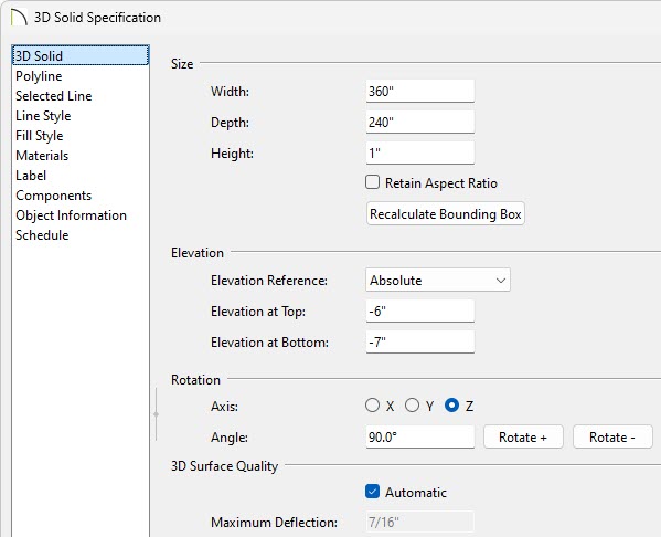
- On the Materials panel, select the 3D/Polyline Solid component, then click on the Select Material button.
- In the Select Material dialog, browse to Chief Architect Core Catalogs> Materials> Landscaping and Roadways> Water, and choose a water material.
In this example, Water1 is used.
- Click OK and OK again to close the dialog and apply your changes.
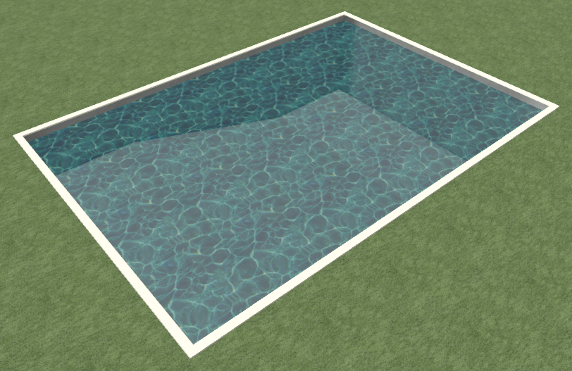
- Finally, take another Perspective Full Overview to see the results.
To accessorize the pool area
A patio area around your pool can be designed using one or more terrain features with different heights and materials. Avoid drawing a terrain feature over the pool feature, as it will cover it up.
Suitable patio materials can be found in the library browser by going to Chief Architect Core Catalogs> Materials> Masonry and Stone and the Chief Architect Core Catalogs> Materials> Tile folders.
Furniture, games, and other accessories can also be found in the Library Browser.
Additional poolside objects and materials can be found by accessing the 3D Library.