QUESTION
I see that there is a library catalog of log trusses that can be placed into a Chief Architect plan, but how do I create the roof to go over those trusses, complete with purlins, tongue and groove, and rafters?

ANSWER
Chief Architect is designed to allow you to quickly model conventionally framed structures. A log structure, however, does not fall into the category of conventional framing, so when drawing such a plan, we need to use the program's tools creatively.
This article assumes that the reader is familiar with and comfortable using default settings, creating custom wall types, and using the manual framing and CAD editing tools.
There are several distinct steps to this task:
Before starting work on any drawing, it is important to set up the correct default settings - particularly for the structural aspects of the plan.
As you set up your defaults, you can also set up the default styles and materials for doors, windows, cabinets, and more; however only defaults that affect truss placement and roof structure are discussed in this example.
To prepare to draw the structure
- Select Build> Wall> Define Wall Types
 from the menu, and in the Wall Type Definitions dialog, create a new wall type to represent true log walls.
- In this example, a "Natural Log - [10" Flats]" wall type has been created with three layers: 10 1/2" Main Layer of Fir Framing in the middle and two 3/4" layers of log siding on either side of it.
- For more information about how to create custom wall types, see the Related Articles section below.
- Select Edit> Default Settings
 from the menu to open the Default Settings dialog.
- On the Locate Objects panel of the Dimension Defaults dialog:
- Under Walls, Click the radio button next to Surfaces.
- Check the box under Fixtures/Appliances beside Sides/Corners.
- On the Structure panel of the Floor 1 Defaults dialog, under the "Relative Heights" heading, specify the desired Rough Ceiling height. In this example, 108" is used.
- In the Exterior and Interior Wall Defaults dialogs, specify the wall types that you require for your project.
- Select Build> Roof> Build Roof
 from the menu. On the Roof panel of the Build Roof dialog:
- Specify the desired Pitch and Roof Overhang. In this example, 12/12 and 18" are used, respectively.
- Be sure to leave the box beside Trusses (no Birdsmouth) unchecked.
- On the Options panel of the Build Roof dialog:
- Uncheck Use Room Ceiling Finish.
- Check the box beside Has Ceiling.
- Specify the desired Thickness of the tongue and groove material you wish to use. In this example, 1 1/2" is used.
- On the Materials panel of the Build Roof dialog:
- Specify the desired materials for the different components of the roof.
- In particular, be sure to specify an appropriate tongue and groove style material for the Ceiling Surface.
Once your defaults are set up, you can draw the structure. In this example, a simple 24' x 30' rectangle is used.
- Select View> Library Browser
 from the menu and browse to Bonus Catalogs> Log Truss Components> Full Log Trusses.
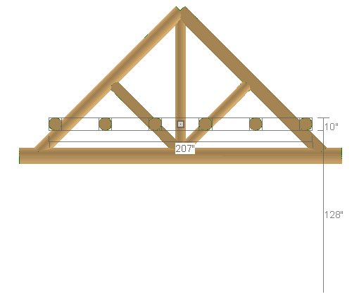
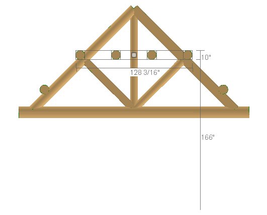
- The truss symbols in this folder are designed to match common width and pitch configurations.
- These symbols can be resized, but note that if you do resize one, the pitch of its top chords will change.
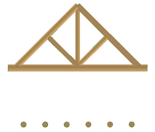
- Select a truss that meets your needs, then click once in the drawing area to place a copy at that location.
- In this example, the 24' 12/12 Log Truss is used.
- The other folders in the Log Truss Components catalog contain items that can be used to create custom log trusses. For information about creating a custom log truss, see the Related Articles section below.
- Click the Select Objects
 button, select the truss and:
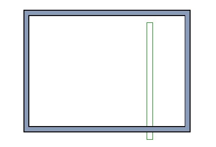
- Rotate it as needed.
- If you placed the truss outside of the structure, you will also need to move it into the interior. If it bumps into the walls, hold down the Ctrl or Command key while dragging to suppress movement restrictions.
- With the truss still selected, click the Open Object
 edit button. On the General panel of the Millwork Specification dialog:
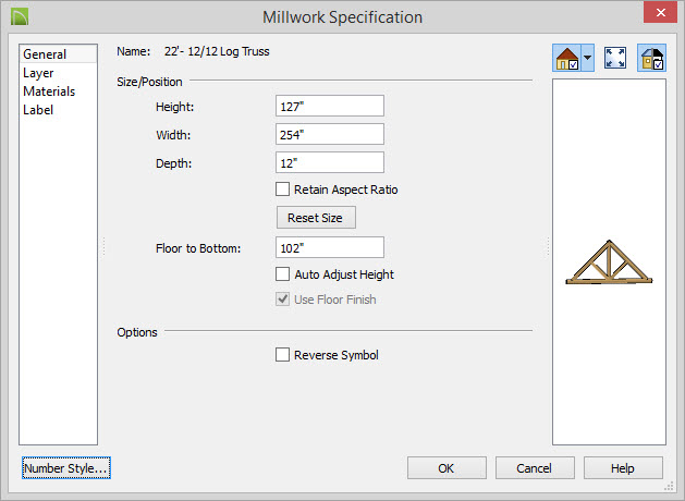
- Specify the desired Floor to Bottom value, then click OK.
- Log trusses often rest in notches cut into the top logs of log walls; so in this example, a Floor to Bottom value of 102" is used.
- With the truss still selected, center it over the structure:
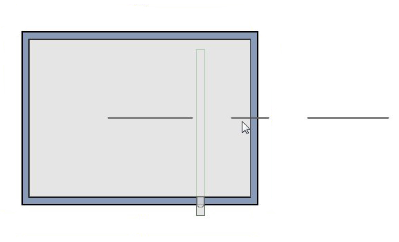
- Click the Center Object
 edit button.
- Move your mouse pointer over the room that you want to center the truss over.
- When the room becomes highlighted and a temporary centering axis displays perpendicular to the length of the truss, click one time.
- Select CAD> Dimensions> Manual Dimension
 from the menu, then click and drag a dimension line from the truss to the nearest parallel wall. Use this dimension to position the truss relative to the wall:
- By default, the dimension will locate the wall's exterior. If you want, you can select the dimension line and use its edit handles to make it locate the wall's interior instead.
- Click the Select Objects button, then click on the truss to select it.
- Move your mouse pointer over the dimension line and when it changes to a hand symbol, click once.
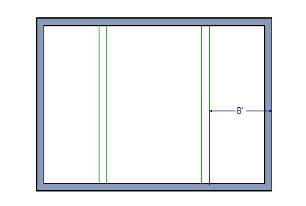
- In the inline text field, type the distance that you would like the truss to be from the wall and then press the Enter key.
- In this example, the dimension line locates the wall's exterior, and a value of 8 feet is used.
- Once the first truss is in place, an array of trusses can be replicated in a variety of ways. In this small example, only one additional truss is needed. To create it:
- Select the truss and click the Copy/Paste
 edit button.
- Click the Reflect About Object
 edit button.
- Move your mouse pointer over the room that the truss is over.
- When the room becomes highlighted and a temporary centering axis displays at the center of the room and parallel to the length of the truss, click one time.
- A second truss will be created on the other side of the room, the same distance from the center as the original.
With the trusses in place, purlins can be created.
- In the Library Browser , browse to Bonus Libraries> Log Truss Components> Individual Logs.
- Select the 10" Log (R-90), then move your mouse into the drawing area and click one time to place a copy.
- The Individual Logs can also be used to create custom log truss symbols. When using them as purlins, be sure to select items with either (R-90) or (R-00) in the name.
- If necessary, rotate the log purlin so that it is perpendicular to the trusses in your plan, and then move it into position inside the structure.
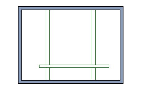
- Hold down the Ctrl/Command key to override movement restrictions.
- Do not worry about exact placement right now - the truss will be moved into position using dimensions in a moment.
- With the log purlin still selected, click the Open Object edit button. On the General panel of the Millwork Specification dialog:
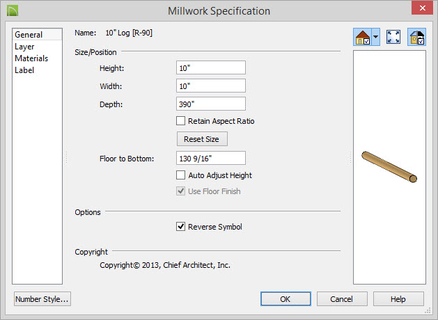
- Specify the desired Depth (if the symbol you are using has (R-00) in the name, instead specify its Width.
- This value should equal the length of the room plus the depth of the roof eaves. You may want to reduce this total to provide a gap between the ends of the purlins and the eave edges.
- In this example, a value of 390" is used. This is equal to 30' plus 18" for the eaves on each side, minus 3" on each end.
- With the purlin still selected, center it lengthwise over the room:
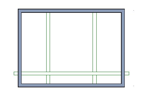
- Click the Center Object edit button.
- Move your mouse pointer over the room.
- When the room becomes highlighted and a centering axis displays perpendicular to the length of the purlin, click once.
- Select Edit> Snap Settings
 from the menu.
- Confirm that Center
 has a checkmark next to it and is enabled.
- If Midpoint
 has a checkmark next to it, select it to turn it off.
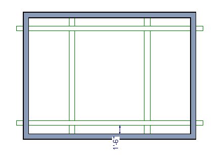
- Select CAD> Dimension> Manual Dimension from the menu, then click and drag a dimension line from the purlin to the nearest parallel wall. Use this dimension line to position the purlin relative to that wall:
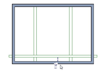
- Click the Select Objects button.
- Move your mouse pointer over the dimension. When it turns into a hand, click once.
- In the inline text field, type the desired distance that you want the purlin to be from the wall.
- In this example, 18" is used.
- With the purlin still selected, use the Copy/Paste and Reflect About Object edit tools to create a copy on the other side of the room, as described above.
- With the new perlin selected, click the Multiple Copy
 edit button, and then click the Multiple Copy Interval
  edit button. In the Multiple Copy dialog:
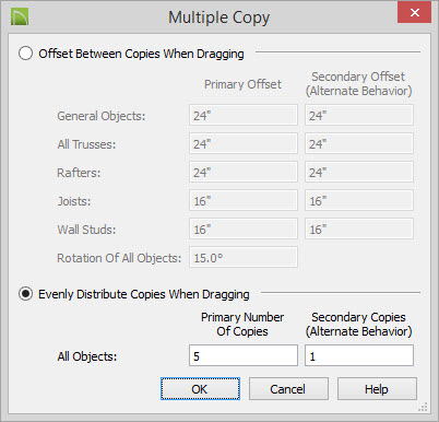
- Click the radio button beside Evenly Distribute Copies While Dragging.
- Specify the Primary Number of Copies value as equal total number of purlins that you need, minus one.
- Click OK.
- The selected purlin will now have only one edit handle. Click this Move edit handle and drag across the structure.
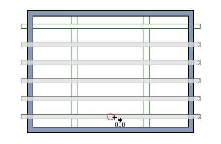
- As you drag, the specified number of purlins will appear and will spread out in regular intervals as the distance you drag increases.
- When your mouse pointer reaches the original purlin in the drawing, you can snap to its Center point. When you see the Center snap indicator, release the mouse button to create the array of purlins.
- When you release the mouse button, only the last purlin in the array will be selected. It is located in the same position as the original, so you should Delete
 it.
it.
The easiest way to set the purlins' heights is in an elevation view.
To set the purlins' heights
- Select 3D> Create Orthographic View> Cross Section/Elevation
 from the menu, then click and drag a camera arrow on the exterior of the structure, parallel to the purlins.
- Click the Active Layer Set Control drop-down and select "3D Framing Set" from the list.
- Select Tools> Layer Settings> Display Options
 from the menu, and in the Layer Display Options dialog, turn on the display of the "Millwork" layer and click OK.
- Click the Select Objects edit button, then hold down the Shift key and click on each of the purlins to select them as a group.
- Use the selected set's Move edit handle to move the selected purlins straight up until they are at the height of the trusses.
You can make fine adjustments to their height using the Transform/Replicate Object  edit tool. Changes in height are made using the Z Delta setting.
- With the purlins still selected, hold down the Shift key and click on the two outermost purlins to remove them from the selection set.
- Repeat steps 5 and 6 to position the remaining purlins.
- When the purlins are all in place, select File> Close View to close the elevation view and return to floor plan view.
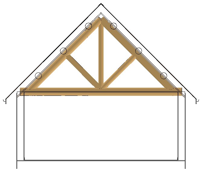
With trusses and purlins all in place, the roof can be built over them.
To build the roof
- Group select the two shorter walls and click the Change to Gable Walls
 edit button.
- Select Build> Roof> Build Roof from the menu. On the Roof panel of the Build Roof dialog, check the box beside Build Roof Planes and click OK.
- Select 3D> Create Orthographic View> Backclipped Cross Section
 from the menu, then click and drag a camera arrow perpendicular to and through one of the trusses.
- Select CAD> Dimensions> Tape Measure
 from the menu, then click and drag a temporary dimension line to get a sense of how far the purlins extend into the roof above.
- If you need to adjust the height of the roof, there are several ways you can do it:
- Specify the Raise/Lower From Ceiling Height value in the Build Roof dialog, and then rebuild the roof.
- Select Build> Roof> Edit All Roof Planes
 from the menu, lock the roof Pitch, and adjust the Baseline Height. This is not advisable if your roof planes have more than one baseline height.
- Group-select all roof planes and use the Transform/Replicate Object edit tool to adjust their height.