QUESTION
When I take a 3D camera, overview, or elevation view of my structure, I see the siding, brick, stone, drywall, or another wall material displayed inside of the windows and vents. What is causing the software to do this, and how can I fix it?
ANSWER
The exterior or interior wall materials can display inside of windows and gable attic vents if a wall is building up through them, either due to the wall's top or bottom being modified in a camera view, or if there is a wall misalignment between floors, typically caused by a slightly off-angle wall.
To troubleshoot siding displaying in windows and vents
- While in the 3D camera or cross section view that demonstrates the siding going through the window, use the Select Objects
 tool to select the wall.
If the Status Bar indicates that the Exterior Room is selected, press Tab on the keyboard, or click the Select Next Object edit tool to select the individual wall.
- Click on the Open Object
 edit button.
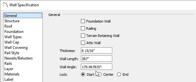
- On the General panel of the Wall Specification dialog that opens:
-
Make a note of the Wall Angle.
-
If the angle appears to be slightly off of what it should be by several decimal places, correct this value.
For example, this wall should have a Wall Angle of 180 degrees.
-
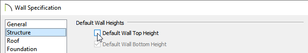
Next, select the Structure panel:
-
Under the Default Wall Heights section, check the Default Wall Top Height and/or Default Wall Bottom Height boxes.
-
If these values are greyed out and inactive, it means that they are already set at their default values.
-
Consider repeating this process on walls that may be located directly above or below the wall that is currently open to specification.
-
Click OK to apply these changes to the wall and return to the 3D camera or cross section view where the wall should still be selected.
-
Finally, click the Align with Wall Above
 or Align with Wall Below
  edit buttons, if one of these is available, to align the modified wall with the other floor in the design.
-
If you experience trouble with following these instructions, or they do not resolve the issue in your particular plan, then please submit the plan file to our Technical Support team using the Technical Support Center. Instructions on this process can be found in the Related Articles section below.