This article also applies to the following legacy products:
Pro
QUESTION
I have walls drawn at off angles in my design. Is there an easy way to draw additional walls at a particular angle value or increment?
ANSWER
The angle increment, as well as additional, custom snap angle values can be specified in the General Plan Defaults. This allows for line-based objects, such as walls, to be drawn at specific angles as long as Angle Snaps are enabled.
Angle increments will only work with Angle Snaps enabled. You can toggle Angle Snaps by navigating to Edit> Snap Settings> Angle Snaps. When Angle Snaps are disabled, an icon will follow your cursor signifying that they are disabled, which is often undesired. To learn more about snaps and behaviors, please access the "Working with Edit Behaviors" resource in the Related Articles section below.
This article will cover the following:
After importing a DWG of a floor plan that contains walls or lines at off angles, it may be necessary to first determine the angle value of the components. To do so, follow the instructions in the first or second section below.
To determine the angle using the object specification
- Using the Select Objects
 tool, click on the line and use the Open Object
  edit tool to open the Line/Polyline Specification.
- In the Line Specification, on the Line panel take note of the Angle, as it is the angle we will add as an allowed angle.
In the Polyline Specification, on the Selected Line panel take note of the Angle, as it is the angle we will add as an allowed angle.
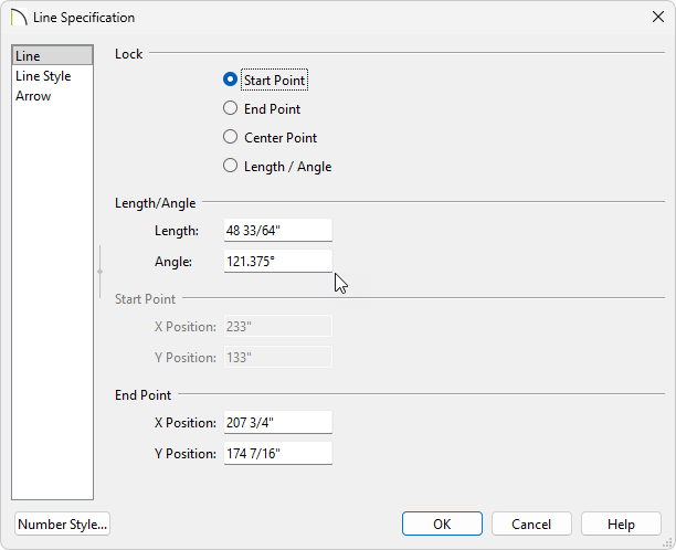
- Click OK to close the dialog.
Additionally, you could use the Angular Dimension tool to measure the angle of the selected line.
To determine the angle using the angular dimension tool
- Select CAD> Lines> Draw Line
 and use the Draw Line tool to draw a horizontal line from your angled line.
![]()
- Select CAD> Dimensions> Angular Dimension
 to select the tool.
- Click and drag from your horizontal line to the off angled line to create a dimension.
- Using the Select Objects tool, click on your horizontal line and then click into the drawn angular dimension value to open the Set Angular Dimension dialog.
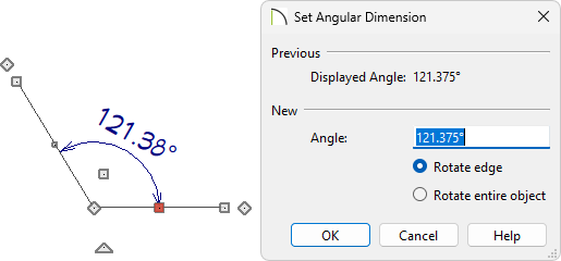
- Take note of this angle, as it is the angle we will add as an allowed angle.
Now that we have our needed angle, we are ready to add it as an allowed angle.
To add the angle as an allowed angle in your general plan defaults
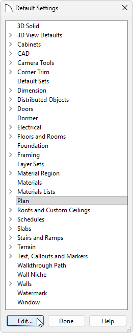
- Go to Edit> Default Settings
 , and in the Default Settings dialog that displays, select Plan, then click Edit.
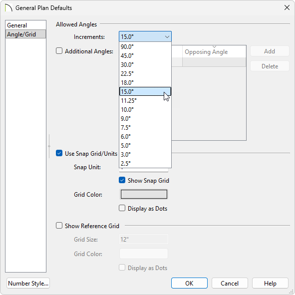
- On the Angle/Grid panel of the General Plan Defaults dialog that displays, an Increments drop-down is available, where several predefined options are located; select your desired value from the list, of which will be used when Angle Snaps are enabled.
In Chief Architect X16, Home Designer 2025, and prior versions, the only predefined options that are available are 15 Degrees and 7 1/2 Degrees.
- Check the Additional Angles box and click in an empty cell within the Additional Angle column to input a custom angle value that your line/wall needs to be drawn at.
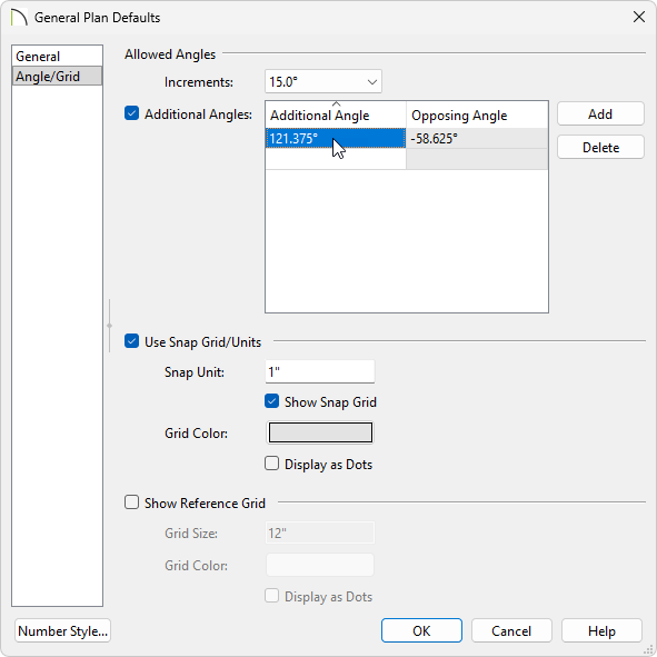
- Click OK and Done to close and save your changes.
- Now, when the Draw Line or a Wall
 tool is used, the specified angle value will be recognized.