The Add Break edit tool can be used to create two types of breaks: partial breaks and complete breaks.
Tools & Techniques
276 - Using the Space Planner
252 - Centering Objects
302 - Multiple Copy
303 - Using the Break Tool
254 - Using Construction Lines
5429 - Positioning and Resizing Objects Using Dimensions
2432 - Adding Watermarks
304 - Merging Polylines that Overlap
305 - Subtracting Polylines that Overlap
306 - Using the Trim and Extend Commands
267 - Using the Point to Point Move tool
5307 - Using the Object Eyedropper and Painter
247 - Using Style Palettes
10197 - Productivity Tips
1598 - Using the Library Painter
193 - Offsetting the Reference Display
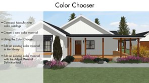
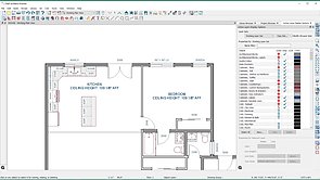
37 - Color Chooser
264 - Displaying Coordinate Axes
925 - Stretch Zones and Planes
5413 - Edit Behaviors
10096 - Designing and Selling with 3D Software
5225 - Importing and Managing PDF and Picture Files
61 - Controlling the Drawing Order of Objects
1924 - Using Macros in Object Labels
CAD Tools
5479 - Using CAD Detail From View for Details
77 - CAD Basics
5441 - Drawing CAD Points, Lines and Splines
5443 - Drawing CAD Polylines and Boxes
270 - Drawing Arcs
5310 - Fillet and Chamfer Tools
2434 - Using the Stretch CAD Tool
269 - Specifying Line Styles
46 - Adding Detail to Cross Section Views
2425 - Converting CAD to Distribution Paths or Regions
2424 - Distributing Objects Along a Path or Region
1922 - Adding Insertion Points to CAD Blocks
1930 - Creating a Site Plan or Plot Plan
1945 - Floor Plan Line Weights, Fills, and Space Planning Indicators