QUESTION
I have a DWG file containing terrain data that I received from my surveyor or engineer. How do I import this into my design?
ANSWER
Importing terrain data from a DWG or DXF file is a straight-forward task, though it requires some knowledge of what layers were used when the drawing was created and which layers contain the data that you need.
Terrain drawings typically contain several types of data, specifically lot boundary data, elevation/contour data, and other CAD data such as text. There is no single CAD standard, and which layers the different data is on is determined by who created the drawing.
In this article, we will discuss the following topics:
To determine which layers contain pertinent terrain data
- In the plan you'd like to import the DWG into, select File> Import> Import Drawing (DWG, DXF)
 from the menu.
- Find the file on your system, select it, and choose Open.
In Chief Architect Premier X17 and newer, you can select multiple DWG files to import more than one at a time.
In X16 and prior versions, in the Import Drawing Assistant dialog that displays, click Next or Continue to go to the Select File portion of the dialog, then use the Browse button to browse to the DWG or DXF file's location on the computer, select it, then click the Open button.
- In the Import Drawing dialog:
If using X16 or prior, skip to Step 4 instead.
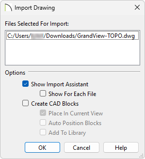
- Check the box for Show Import Assistant.
- Uncheck the box for Create CAD Blocks.
- Click OK.
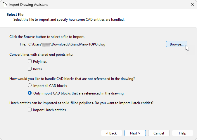
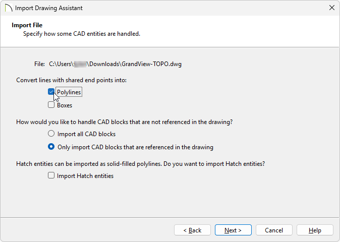
- On the Import File portion of the dialog:
- Do not check Polylines or Boxes under the Convert lines with shared end points section at this time.
- Choose to Only import CAD blocks that are referenced in the drawing.
- You can check the Import Hatch entities box if you'd like to import areas of hatching as solid-filled polylines.
- Click Next or Continue.
-
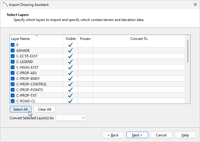
On the Select Layers page, make sure there is a check beside the name of each layer shown in the Layer Name column, then click Next/Continue.
You can click the Select All button to check all layers at once, ensuring that every layer will be imported during this process.
-
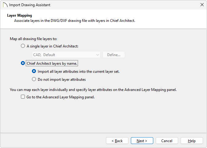
On the Layer Mapping page, select the Chief Architect layers by name. radio button, leave the Import all layer attributes into the current layer set. radio button selected, then click Next/Continue.
-
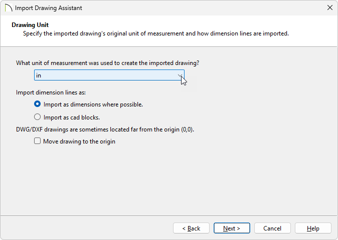
On the Drawing Unit page, select the unit of measurement that was used to create the drawing using the drop-down list, click Next/Continue, then click Finish/Done to close the dialog and import the drawing.
-
You should now see the drawing in the plan. If you do not, select Window> Fill Window
 from the menu to center it in the drawing area.
If you still do not see the drawing, please refer to the ADDITIONAL INFORMATION section at the end of this article.
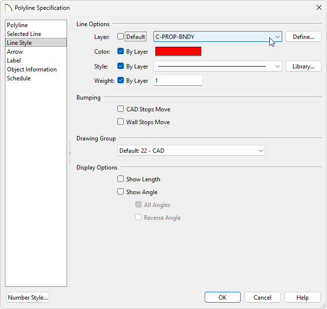
- Click on the polyline representing the lot boundary to select it, click the Open Object
 edit button, then select the Line Style panel of the object's specification dialog. Make a note of the Layer that it is on, then click OK.
In this example, the lot boundary is on a layer called C-PROP-BNDY.
- Next, determine which layer(s) the contour/elevation lines are on using the same technique just mentioned in Step 7.
- Once you have determined the layers that the terrain data is on, close the file without saving it, then proceed to the next section.
To import lot boundary data and elevation/contour data
- In your desired plan, and with the appropriate plan view active, navigate to File> Import> Import Drawing (DWG, DXF) from the menu to open the Import Drawing Assistant, then click Next/Continue.
- On the Select File page, click the Browse button to open the Import Drawing File dialog and select the desired DWG or DXF file saved on your computer. Once the desired file is selected, click Open to return to the Import Drawing Assistant. Check the Polylines box under the Convert lines with shared end points into: heading, then click Next/Continue.
- On the Select Layers page:
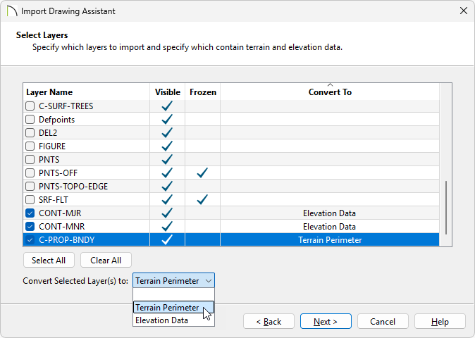
- Uncheck any unwanted layers using the Layer Name column. You can click the Clear All button to quickly, and easily, uncheck all layers at once.
In this example, the CONT-MJR, CONT-MNR, and C-PROP-BNDY layers are the only layers selected.
- Select the layer containing the lot boundary polyline, then select Terrain Perimeter from the Convert Selected Layer(s) to drop-down list.
In this example, the C-PROP-BNDY layer is the lot boundary layer and is specified to be converted to the Terrain Perimeter.
- Select the layer(s) that contain contour/elevation data and select Elevation Data from the Convert Selected Layer(s) to drop-down list.
In this example, the CONT-MJR and CONT-MNR layers consist of minor and major contour/elevation data and are specified to be converted to Elevation Data.
- Once the correct layers are selected and defined correctly, click Next/Continue.
- On the Layer Mapping page, select a layer mapping option. Any option will work in this instance; however, you can, for example, map the lot boundary directly to the native Chief Architect Terrain Perimeter layer by checking the box beside Go to the Advanced Layer Mapping panel, then clicking Next/Continue.
-
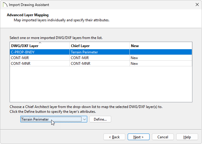
(Optional) On the Advanced Layer Mapping page, click on the layer(s) that you would like to remap, then use the drop-down menu at the bottom to map the layer(s) to the desired Chief Architect layer(s). Once the layers are mapped to your liking, click Next/Continue.
In this example, the C-PROP-BNDY layer is mapped to the Terrain Perimeter layer. You could also map the contour/elevation layers to native Chief Architect layers at this time.
You can also click on the Define button located beside the layer drop-down option to open the Layer Display Options dialog, where additional layer properties can be adjusted.
- On the Drawing Unit page, select the desired unit of measurement, click Next/Continue, then click Finish/Done to close the dialog and import the drawing.
-
You should now see the drawing in the plan. If you do not, select
Window> Fill Window from the menu to center it in the drawing area.
If you still do not see the drawing, please refer to the
ADDITIONAL INFORMATION section at the end of this article.

-
Additional changes to the terrain perimeter and elevation data can now be made.
- Once your desired changes are complete, navigate to Terrain> Build Terrain
 from the menu, then take a Camera
  view to see the results.

To import other CAD data
-
- Navigate to File> Import> Import Drawing (DWG, DXF) from the menu to open the Import Drawing Assistant, then click Next/Continue.
- On the Select File page, click the Browse button to open the Import Drawing File dialog, select the desired DWG or DXF file saved on your computer, then click Next/Continue.
- On the Select Layers page, select layers not containing perimeter or elevation data by unchecking the layers that were already imported, then click Next/Continue.
- Choose your desired options on the Layer Mapping page, then click Next/Continue.
-
On the
Drawing Unit page, select the unit of measurement, click
Next/Continue, and finally,
Finish/Done. You should now see the additional data in your plan.

ADDITIONAL INFORMATION
- Drawings imported into Chief Architect should be created in Model Space in AutoCAD®. If a drawing was created on Page 1 in Paper Space, it will be imported as it's own CAD block.
- Chief Architect does not recognize layers that are frozen in AutoCAD®. You can see if any layers in your drawing file are frozen on the Select Layers page of the Import Drawing Assistant.
- Chief Architect is able to import layers that have been turned off in AutoCAD®; however, the 2D display of these layers will be turned off in Chief Architect, as well, so you will not see them when the drawing is first imported.
- Elevation data saved in a text file format can also be imported by selecting File> Import> Import Terrain Data
 from the menu. Elevation data that is saved in this format is usually done with the x, y, and z coordinates in mind, where x and y define the location of a point on a Cartesian grid, and z defines the elevation for the point. When using this import method, each data point must be on a separate line in the text-based file.
For more information, navigate to Help> Launch Help  within your program, and search: Import Terrain Assistant.
- GPS data in a .gpx file format can also be imported by selecting File> Import> Import GPS Data
 .GPS data may include three types of points - Way, Track and Route. Chief Architect can only import a .gpx file if it includes one or more Way Points. If a *.gpx file is imported and it contains no Way Points, no data will be imported. Route Points contained in a .gpx file will not be recognized upon importing.
For more information, navigate to Help> Launch Help within your program, and search: Import GPS Data Assistant.