The information in this article applies to:

QUESTION
I need to manually modify deck framing that Chief Architect created in my plan. What are my options?

ANSWER
When a room is defined as a Deck in Chief Architect, framing is generated automatically. This is a fast way to generate posts, beams, joists and planking, but sometimes manual modifications may still need to be made.
In this article, we will cover the following topics:
To create the initial structure
- Select File> New Plan
 to open a new, blank plan.
- Select Build> Wall> Straight Exterior Wall
 , then draw exterior walls forming a perimeter, making sure to create a fully enclosed space.
- Select Terrain> Create Terrain Perimeter
 to create a flat terrain pad.
- Next, navigate to Terrain> Terrain Specification
 from the menu.
-
On the General panel of the Terrain Specification dialog that displays, remove the check from the Automatic box beside Subfloor Height Above Terrain, change the Subfloor Height Above Terrain value, then click OK.
- Select Build> Floor > Build Foundation
 to open the Build Foundation dialog.
- On the Foundation panel, select Walls with Footings as the Foundation Type, specify the Minimum Height under the Stem Wall section, then click OK.
For information on creating a walkout basement in sloping terrain, please see the Related Articles section below.
- Go Up One Floor
 to Floor 1, select Build> Railing and Deck> Straight Deck Railing
  and draw railings to enclose one or more Deck rooms attached to the structure.
- Using the Select Objects
 tool, click in an empty space in the Deck room to select it, then click the Open Object
  edit button.
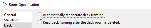
- On the Deck panel of the Room Specification dialog that opens, uncheck Automatically regenerate deck framing, then click OK.
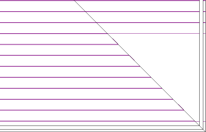
To adjust deck planks
- With the CAD> Lines> Draw Line
 tool, create a line at the corner where the miter should be.
In X12 and prior versions, framing ends will be square even if trimmed on an angle.
- Select the CAD line and click the Trim Object(s)
 edit button.
- Click and drag a temporary line, or fence, that runs through the deck planks on one side of the miter CAD line.
In X14 and newer versions, the deck planks will highlight for the portion that will be kept after trimming.
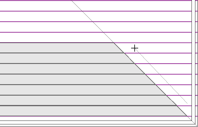
- When you release the mouse button, the ends of the planks will be trimmed back to the inside edge of the CAD line.
- Repeat these steps for any other areas where the planks need to be mitered, and use the edit handles to extend the length of the planks as necessary.
- When you are finished, you can select 3D> Create Perspective View> Full Camera
 to see the results.
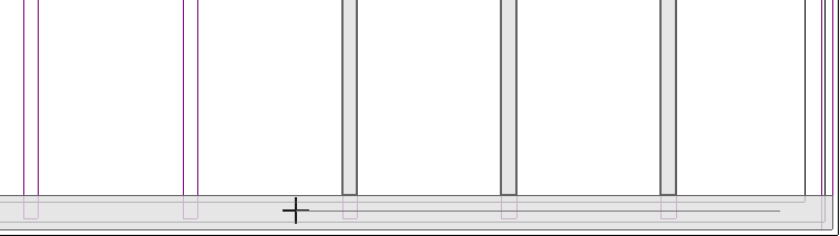
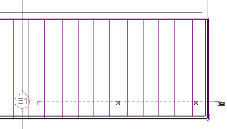
To adjust deck joists
- Select one or multiple joists with Select Objects .
Hold down the Shift key on your keyboard and click on another framing member to add it to the selection set. For more information on group selecting objects, please see the Related Articles section below.
- Click Edit> Delete
 or the Delete key on your keyboard to remove the joists that aren't necessary.
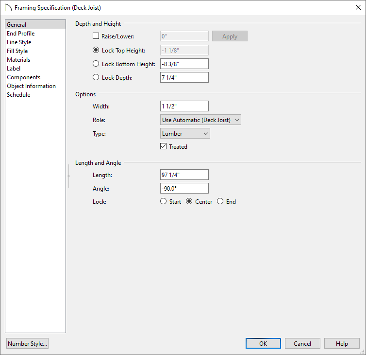
- With the joists still selected, use the edit handles to change their location.
- Click on Open Object to adjust the Bottom Height, Depth, Width, Role*, and Type.
*Only available in X14 and newer program versions.
- Select the beam and click the Trim Object(s) edit button. These steps also work with a CAD line.
- Click and drag a temporary line, or fence, that runs through the joists where they extend into the beam.
In X14 and newer versions, the deck joists will highlight for the portion that will be kept after trimming.
- When you release the mouse button, the ends of the joists will be trimmed back to the inside edge of the beam.
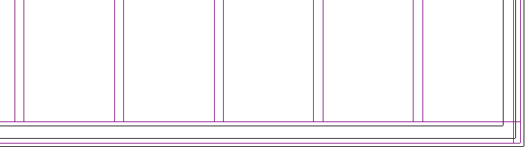
- When you are finished, you can select 3D> Create Perspective View> Full Camera to see the results.
To adjust deck beams
- Using the Select Objects tool, click on a beam that runs under the Deck room.
- Click the Delete edit button or press the Delete key on your keyboard to remove this beam.
- With the beam still selected, use the edit handles to change its location.
- Click the Open Object edit button, and on the General panel of the Framing Specification dialog that displays:
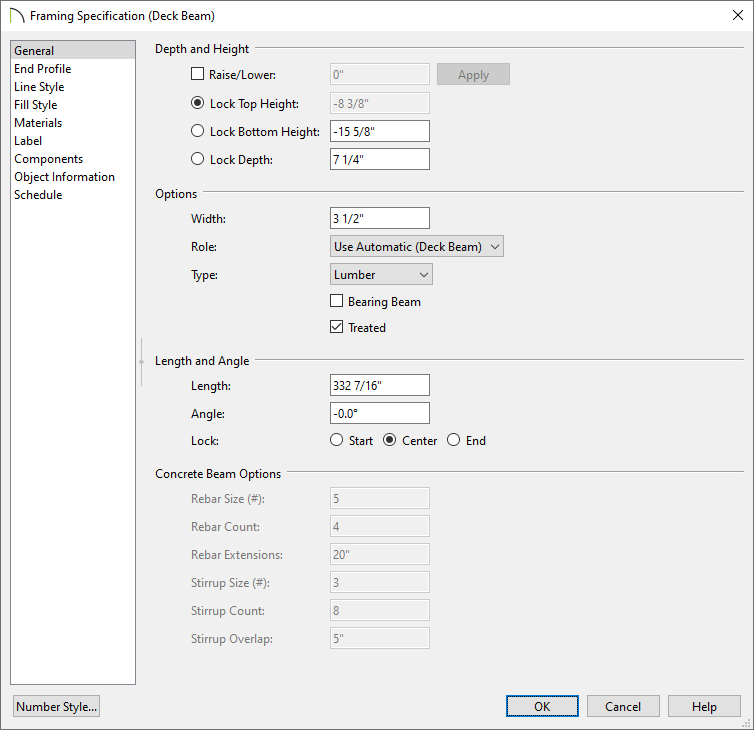
- Change the Top/Bottom Height and Depth.
Use the different Lock radio buttons to keep that field from changing as the other ones are adjusted.
- Change the Width to your liking.
- Change the Type and Role*.
*Only available in X14 and newer program versions.
- Click OK to close the dialog and apply your changes.
The new beam is resized concentrically from the centerline outward, so it may have to be moved to compensate any changes.
To edit posts and footings
- Using the Select Objects tool, click on one of the posts to select it.
- With the post selected, click the Delete button or the Delete key on your keyboard.
- Repeat step 1 and 2 for any footings that need to be removed.
- Select any posts that need to be edited and select the Open Object edit button.
- On the General panel of the Framing Specification dialog:
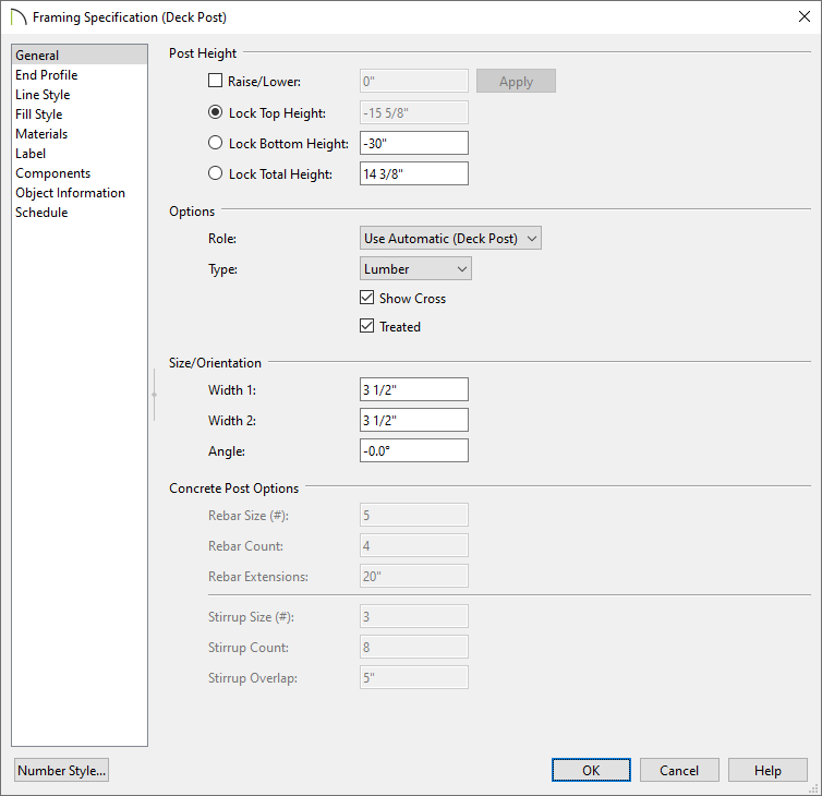
- Set the Top Height, Bottom Height, and/or Total Height.
Use the different Lock radio buttons to keep that field from changing as the other ones are adjusted.
- Set the Role* and the Type.
*Only available in X14 and newer program versions.
- Specify both of the post Width values to fit your needs.
- Click OK to close the dialog and apply your changes.
-
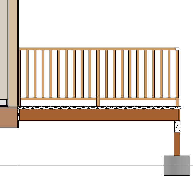
In order to make sure everything is positions correctly, click on
3D> Create Orthographic View> Cross Section/Elevation 
.
- Click where the camera view should start and drag through the deck.
- In the view, select any framing members that are not in the correct positions and use edit handles and/or dimensions to move these members into the correct location.
To add end profiles*
*Only available in X13 and newer program versions
- With Select Objects
 , select the framing member(s) that you'd like to add end profiles to.
- Click on Open Object and on the End Profile panel of the Framing Specification dialog:
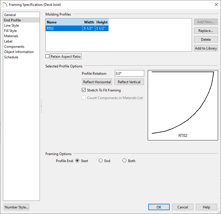
- Click the Add New button to select a molding profile to use at the end profile.
- Set the Width and Height of the molding profile.
- Adjust the Profile Rotation and/or Reflect Vertical/Horizontal as necessary.
- Set whether the end profile needs to be on the Start, End, or Both.
- Click OK to save your changes and close the dialog.