QUESTION
When I click on a CAD polyline, I see the Fillet Lines and Chamfer Lines buttons on the Edit toolbar. What do these tools do, and how can I use them?
ANSWER
The Fillet Lines and Chamfer Lines edit tools allow you to easily add fillets, or curves, and chamfers, or angled edges, to the corners of CAD-based objects, including text. These two tools are particularly helpful because they allow you to produce fillets and chamfers at sizes that you specify.
Some CAD-based objects, such as custom countertops and slabs, can also be edited using these tools.
To use the Fillet Lines edit tool
- Using the Select Objects
 tool, click on a CAD polyline to select it.
- Click on the Fillet Two Lines
 edit tool, then click on the Set Fillet Radius
  secondary edit tool.
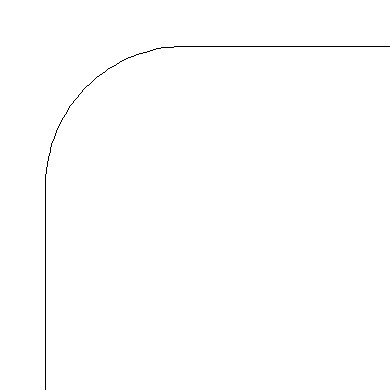
- In the Set Fillet Radius dialog that displays, specify the desired Fillet Radius for the fillet, or rounded corner, that you would like to create.
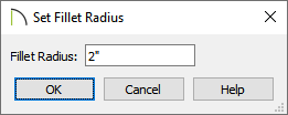
- The fillet radius is the distance from the curve of the fillet to its center point.
-
- A small Fillet Radius value produces a small, tight fillet, and a larger value produces a wider, longer curve. If this value is 0, no fillet will be created.
-
- Once an appropriate value is specified, click OK.
- With the polyline still selected, click on an edge adjacent to the one that you clicked on in step 1. The corner at which the two edges join will become filleted. The fillet radius will now be remembered.
In X14 and newer program versions, edit feedback will display when hovering over an adjacent line with the edit tool selected, allowing you to see what the result will be prior to clicking.
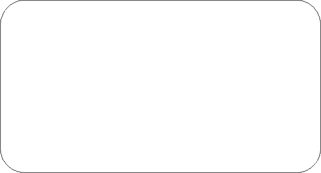
You can also select the Fillet All Corners  secondary edit tool to apply the specified radius to all corners of the selected polyline.
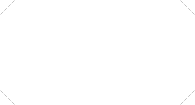
To use the Chamfer Lines edit tool
- Using the Select Objects tool, click on a CAD polyline to select it.
- Click the Chamfer Two Lines
 edit tool, then click on the Set Chamfer Distance
  secondary edit tool.
- In the Set Chamfer Distance dialog that displays, specify the desired Chamfer Distance.
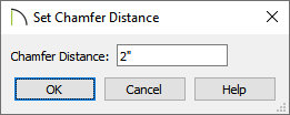
- The chamfer distance is the length of the chamfer, or angled corner.
- Once an appropriate value is specified, click OK.
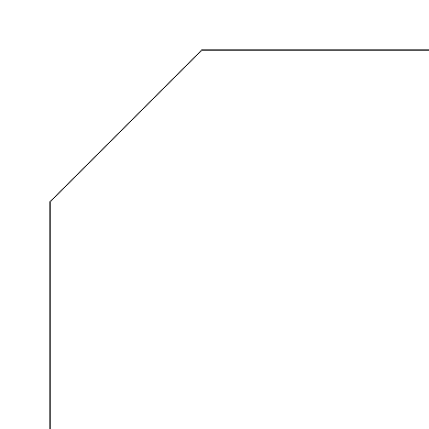
- With the polyline still selected, you can click on an edge adjacent to the one that you clicked on in step 1. The corner at which the two edges join will become chamfered.
In X14 and newer program versions, edit feedback will display when hovering over an adjacent line with the edit tool selected, allowing you to see what the result will be prior to clicking.
You can also select the Chamfer All Corners  edit tool to apply the specified radius to all corners of the selected polyline.