QUESTION
I would like to create a deck with angled deck planking and border planks. How can I customize deck planking and framing?

ANSWER
When a Deck room is created, the floor platform is modeled using joists, beams, posts, and planking as specified in the Deck Room Type Defaults dialog.
-
If a floor is present below the one that the Deck room is created on, the framing will be created there. If needed, posts for the deck may be generated beneath any beams that are generated.
-
If a floor is not present below the Deck, framing will be generated on the same floor as the room. Beams may be created but posts will not.
-
Deck framing, planking, beams, posts, and footings are placed on their own respective layers, which are turned off by default in floor plan view.
-
For changes made to the Structure, Deck, and Deck Support panel to take effect you will need to rebuild the deck framing. This can be done by either checking the Automatically regenerate deck framing box located on the Deck panel, or by selecting the room using the Select Objects
 tool and selecting the Build Deck Framing
  edit tool.
- End profiles can be added to framing members, and the Trim
 and Extend
  tools can be used to clip framing ends at an angle. To learn more about these features, please see the Related Articles section below.
In this article, we will cover the following topics:
Editing deck plank/joist attributes
- Using the Select Objects tool, click in the deck room, then click the Open Object
 edit button.
- In the Room Specification dialog, select the Structure panel.
- Like other rooms here, you can adjust your Ceiling and Floor values on this panel, which will be particularly helpful for creating a multi-leveled deck.
- Next to Planks, Joists click Edit to open the Floor Structure Definition dialog where you can edit your deck planks/joists Material, Width*, and Thickness.
In X16 and prior, the Width is located on the Deck panel, which is discussed in the section below.
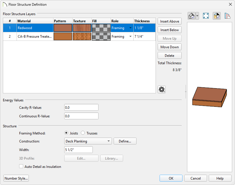
- Once you're finished making changes to your planks/joists, click OK.
If changes are made to the settings on the Structure, Deck or Deck Support panel of the Room Specification dialog, the deck framing, planking, beams, and posts will need to be rebuilt before you will see the changes. Please see the note above for information on rebuilding your deck framing.
Deck panel (deck plank/joist settings)
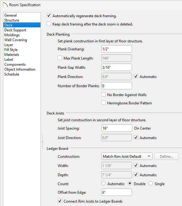
- In the Room Specification dialog, select the Deck panel.
- Editing the information on this panel will control how the deck planking and joists are created.
- The next part of this article will describe how changing each one of these settings affects the deck.
- Once you have made the necessary changes in the dialog, click OK.
If changes are made to the settings on the Structure, Deck or Deck Support panel of the Room Specification dialog, the deck framing, planking, beams, and posts will need to be rebuilt before you will see the changes. Please see the note above for information on rebuilding your deck framing.
Deck Planking
- Plank Overhang
Use this to specify how far deck planking overhangs the joists. In the example below, the value is changed from 1/2" to 1".


- Plank Width
In X17 and newer, this is controlled on the Structure panel by editing your Planks, Joists.
In X16 and prior, this is controlled on the Deck panel.
Use this to specify the width of the deck planking. In the example below, the width is changed from 5 1/2" to 10".


- Plank Gap Width
Use this to specify the width of the gap between each deck plank. In the example below, the width is changed from 1/2" to 1 1/2".


- Plank Direction
This is used to specify the direction of the deck planks. When Automatic is checked, the program will place the deck planking parallel to the longest edge.
In the example below, Automatic is unchecked and the plan direction angle is changed to 45°.


- Number of Border Planks
Use this to specify the number of border planks that will go around the edge of the deck. In X16 and newer, automatic deck framing includes blocking under border planks.
In the example below, this value is changed from 0 to 3.


- No Border Against Walls and Herringbone
- Both of these check boxes are only applicable when border planks are present.
No Borders Against Walls prevents border planking from being generated along any walls defining the deck.
Herringbone produces a herringbone pattern where the border planks meet, instead of miters at the corners.
Examples of each are shown below.


- Checking Treated will set each deck plank as treated in framing schedules and the Materials List.
In X17 and newer, this is controlled on the Structure panel by editing your Planks, Joists, and editing your Deck Planking Construction.
In X16 and prior, this is controlled on the Deck panel.
Deck Joists
-
Joist Width
In X17 and newer, this is controlled on the Structure panel by editing your Planks, Joists.
In X16 and prior, this is controlled on the Deck panel.
- Use this to specify the width of the joists that support the deck planking. In the example below, the width is changed from 1 1/2" to 3".


- Joist Spacing
Use this to specify the distance between the joists that support the deck planking. In the example below, the spacing is changed from 16" to 24".


- Joist Direction
Use this to specify the direction of your joists.
When Automatic is checked, the program looks at the direction of the deck planks and the size of your deck to determine which way the joists will run.
When Automatic is unchecked, and a direction specified, your plank direction will change to accommodate the specified joist direction.
In the example below, Automatic is unchecked and the direction is changed to 45°.


- Checking Treated will set each deck joist as treated in framing schedules and the Materials List.
In X17 and newer, this is controlled on the Structure panel by editing your Planks, Joists, and editing your joist's Construction.
In X16 and prior, this is controlled on the Deck panel.
Ledger Board*
*Available in X18 and newer versions.
- You can control the Construction of the Ledger Board. You can define an custom construction by changing your Construction to Rim Joist and clicking Define.
- You can control the Width and Depth of the Ledger Board by unchecking the Automatic checkbox.
- You can control the Count of the Ledger Boards by choosing either Automatic, Double, or Single.
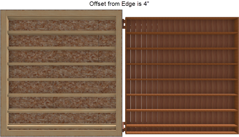
- You can adjust the Offset from Edge, which is the ledger board's distance from the attachment wall layer, specified for each Wall Type.
For information on adjusting your Wall Types please see the Related Articles section.
- When Connect Rim Joists to Ledger Boards is unchecked, the Deck platform's rim joist ends attach to the Ledge Board, leaving an exposed gap if there is an Offset from Edge specified. Check this box to connect the Deck rim joists to the attachment wall layer set in the Wall Type Definitions dialog.
Deck Support panel (deck beam, deck post, and deck post footing settings)
- In the Room Specification dialog, select the Deck panel.
- Editing the information on this panel will control how the deck beams, posts, and deck post footings are created.
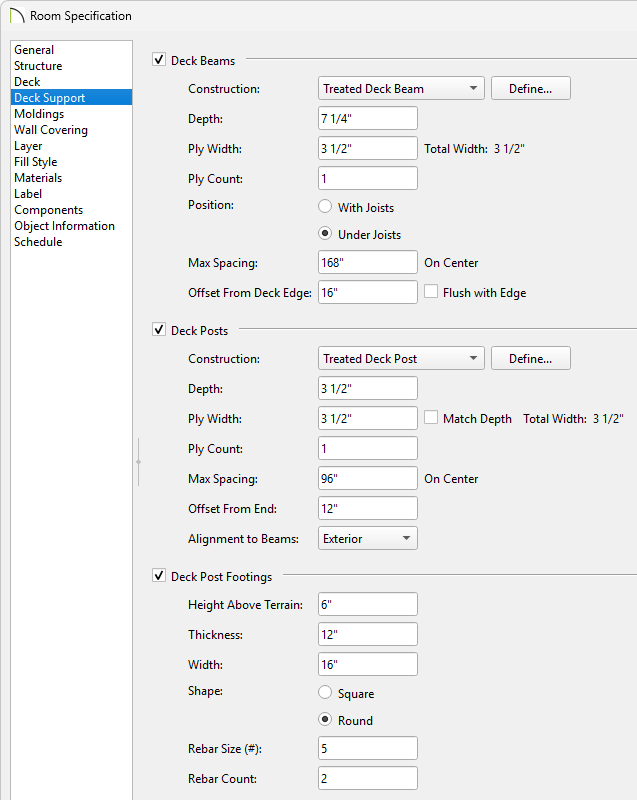
- The next part of this article will describe how changing each one of these settings affects the deck.
- Once you have made the necessary changes in the dialog, click OK.
If changes are made to the settings on the Structure, Deck or Deck Support panel of the Room Specification dialog, the deck framing, planking, beams, and posts will need to be rebuilt before you will see the changes. Please see the note above for information on rebuilding your deck framing.
Deck Posts


