QUESTION
How do I create a brick soldier course around a window and a sloped brick sill in Chief Architect?

ANSWER
A soldier course is a set of vertical bricks lined up in a row with the narrow edge facing outward. These can be modeled in Chief Architect using a Symbol Molding.
This article covers:
To create a basic brick with mortar
- Select File> New Plan
 from the menu to open a brand new, blank plan file.
- Select View> Library Browser
 from the menu, then browse the Library to Chief Architect Core Catalogs> CAD Blocks> Detail Components> Brick and choose a brick style from one of the many choices in this section, then click in the plan to place a copy.
- This is used as a template for the size that will be used during construction. If you have a custom size, simply draw it using CAD tools.
- In this example "Engineer modular (depth)" is used.
- Using the Select Objects
 tool, click on the CAD block to select it and click the Explode CAD Block
  edit button to break the block into its individual components.
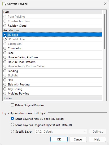
- Select the mortar portion, click the Convert Polyline
 edit button to display the Convert Polyline dialog, move the radio button to 3D Solid, then click OK.
In legacy versions, select the Polyline Solid option instead.
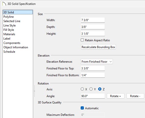
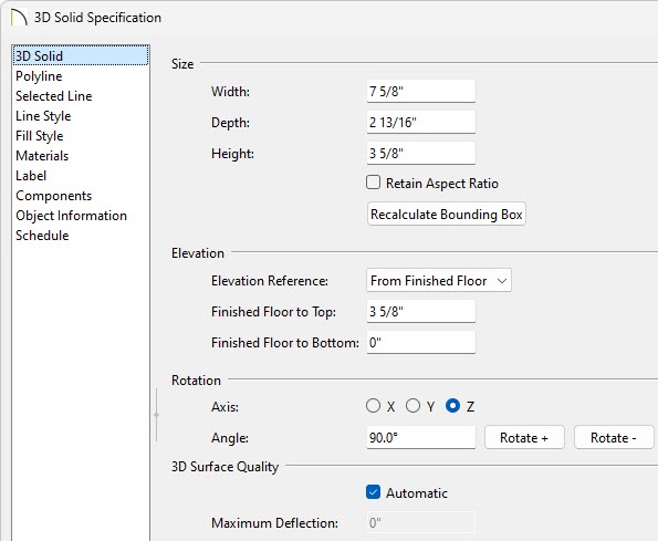
- In the 3D Solid Specification dialog that opens next:
-
On the 3D Solid panel, set the Height to 3 1/8".
In legacy versions, access the General panel and adjust the Thickness instead.
-
Set the Elevation at Bottom or Finished Floor to Bottom to 1/4".
-
On the Materials panel, choose an appropriate material for the mortar.
For the purposes of this example, the default Concrete material is used.
-
Click OK to apply these changes and close the dialog.
-
Repeat Step 4 for the brick portion, and in the 3D Solid Specification dialog that opens:
-
On the 3D Solid panel, set the Height to 3 5/8".
-
On the Materials panel, choose an appropriate material for your brick.
For the purposes of this example, the material is set to "9645 Local Legend - 273 Brick Dust," which can be found in the Mohawk® manufacturer catalog.
-
Click OK to apply these changes and close the dialog.
-
The result should now look like this:

To create a brick and mortar molding symbol
- Select 3D> Create Perspective View> Perspective Full Overview
 from the menu to create a 3D view of the solids making up the brick and mortar.
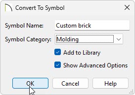
- Select Tools> Symbol> Convert to Symbol
 .
.
-
Specify a Symbol Name.
-
Using the Symbol Category drop-down, select Molding.
-
Check Add to Library and Show Advanced Options.
-
Click OK.
-
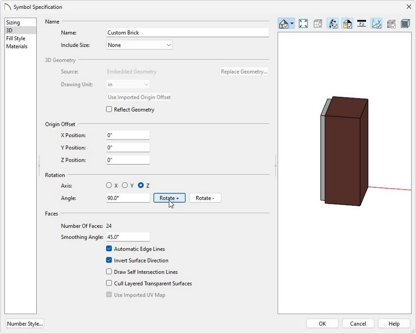
For use as a soldier course, the symbol needs to be rotated, so in the the Symbol Specification dialog that opens next:
![]()
-
On the 3D panel, under the Rotation section, move the radio button to Y, leave the Angle at 90 degrees, then click Rotate + button once.
-
Move the radio button to Z, leave the Angle at 90 degrees, and click Rotate + button once.
-
After rotating the symbol, under the Origin Offset section, set the X, Y and Z Positions all to 0".
-
Click OK to close the dialog and the symbol will be added to the User Catalog.
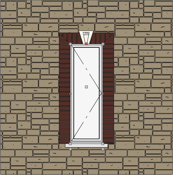
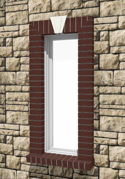
- With this molding now added to your User Catalog, you can use the Build> Trim> Molding Line
 tool with this molding profile applied in a Cross Section/Elevation
  view to quickly create a soldier course around a door or window.
In X15 and prior you will use the Build> Trim> 3D Molding Line tool instead.
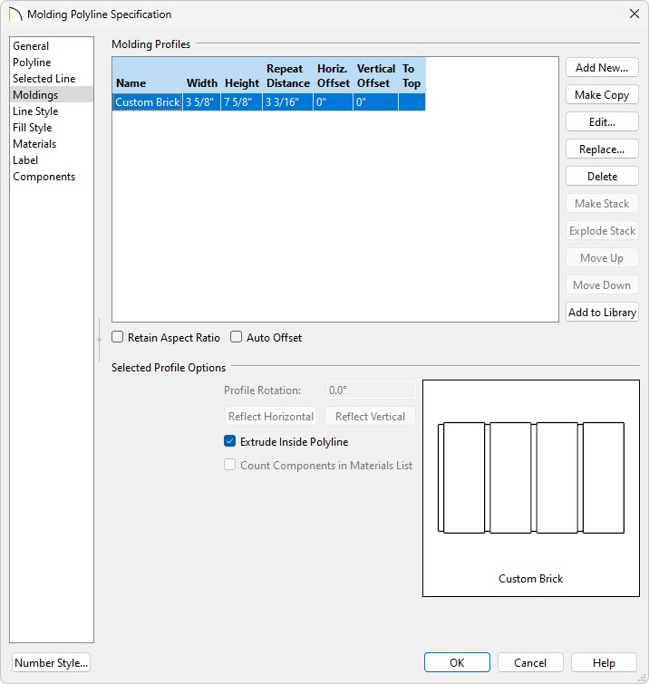
Once the molding profile is applied to the molding line or polyline, the Width, Height, and Repeat Distance values may need to be adjusted. In this example, the Width is set to 3 5/8", the Height is set to 7 5/8", and the Repeat Distance is set to 3 3/16".
A selection of Keystone symbols can be located in the Library Browser by navigating to Chief Architect Core Catalogs> Architectural> Millwork> Keystones.
-
Using the components created earlier, it is possible to create a sloped/angled sill. The next section walks through creating the angled sill as an Architectural Block, which can be added to the Library for use in future plans.
To create an angled sill
- We will now rotate the brick and mortar components at an angle equal to the slope necessary for the sill. To start, select 3D> Create Orthographic View> Cross Section/Elevation from the menu, then click and drag a cross section camera arrow towards the components as shown below.
In legacy versions, you may need to convert the polyline solids that make up the brick to standard solids using the Convert to Solid  edit button.
- Select the concrete solid which represents the mortar, then hold down the Shift key and click on the solid which represents the brick to group select them both. The Status Bar should reflect "2 objects currently selected" near the lower left.
- Click and hold on the object's triangular edit handle and press the Tab key on the keyboard to display the Enter Coordinates dialog.
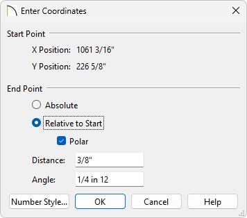
-
Click the Number Style button, change the Angle Style to Pitch and click OK.
- Select Relative to Start and check the box beside Polar.
- Specify your desired Distance.
In this example, a value of 3/8" is specified.
- Specify the desired Angle.
In this example, a value of 1/4 in 12 is specified.
-
Click the Number Style button again, change the Angle Style back to Degrees and click OK.
- Click OK.
-
Close the Cross Section/Elevation View to return to floor plan view.
-
In a floor plan view, use the Select Objects tool to drag a marquee around the solids to group select them, click on the Multiple Copy
 edit button, then select the Multiple Copy Interval
  secondary edit tool.
-
In the Multiple Copy dialog, select Offset Between Copies When Dragging and to the right of General Objects, set the Primary Offset to 3 3/16", click OK, then use the center edit handle to drag up or down and create several copies of the brick and mortar.
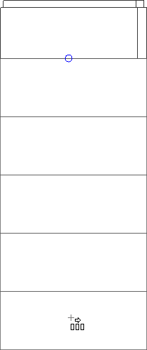
-
Once you have the desired number of bricks copied, select the solid representing the mortar from the end and Delete
 it.
it.
-
Next, drag a marquee around all of the solids to group select them, and click on the Make Architectural Block
 edit tool.
-
This architectural block can now be rotated and placed along your window.
-
To use this in future plans, click the Add to Library
 edit button to add it to your Library Browser where it can then be renamed to your liking.
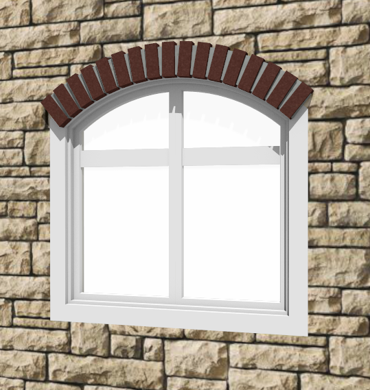
A similar method can be used to create an arched soldier course over a round top window.
To create the brick portion of an arched solider course
-
Open
 the plan with the arched window, then take a Cross Section/Elevation View of the window.
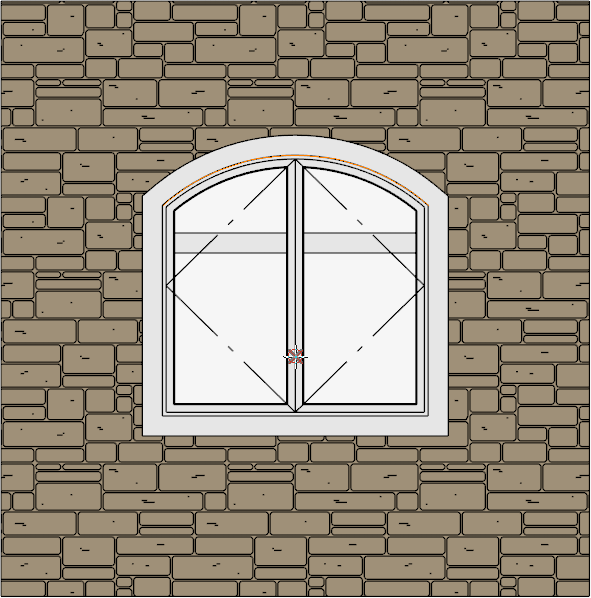
- Select CAD> Arcs> Draw Arc
 , then draw in an arc matching the top of the window.
It may be helpful to change the color of this line so it is more easily visible in the view. For the purposes of this example, the line has been changed to an orange color.
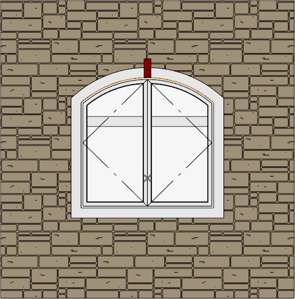
- Next, select View> Arc Centers and Ends
 to toggle the display of Arc centers on, then go to CAD> Points> Place Point
  and click to place a temporary point where the Arc Center is located.
You should then select View> Arc Centers and Ends to toggle the display of Arc centers back off.
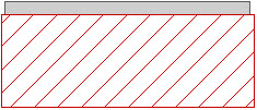
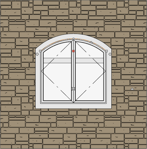
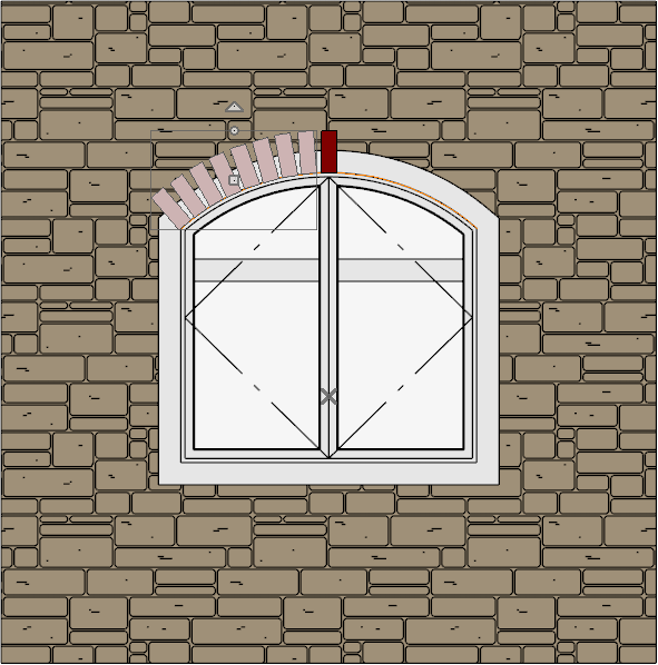
- Next, select CAD> Boxes> Rectangular Polyline
 and draw a rectangle that represents the top brick in the solider course, centering it above the window.
It may be helpful to apply a Solid Fill to the polyline, as shown in the example below.
- Using the Select Objects tool, select the CAD polyline and click on the Transform/Replicate Object
 edit button.
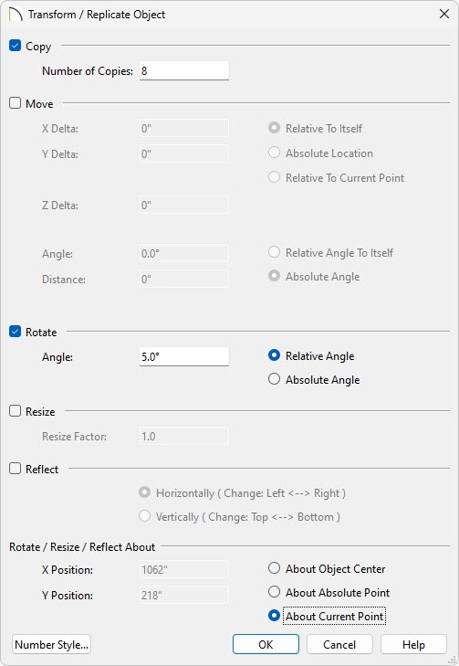
- In the Transform/Replicate Object dialog:
-
Place a check next to Copy and specify the number of copies you want to create.
In this example, a value of 8 is specified.
-
Place a check next to Rotate and set the Angle.
In this example, a value of 5° works well, though this value will vary based on the size of the rectangular polyline and radius of the arc.
-
Under Rotate / Resize / Reflect About, move the radio button to About Current Point, then click OK.
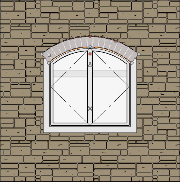
- Now observe rectangular polylines replicated along one side of the arc, as shown in the image below.
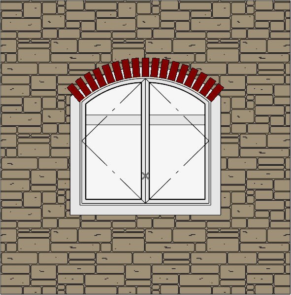
- Select the top rectangular polyline again and use this same method to replicate rectangular polylines along the right side, this time specifying a value of -5° for the Rotate value.
-
Select the polyline furthest to the left, then hold down the Shift key on your keyboard and click to select all of the remaining rectangular polylines to group select them.
-
Click on the Convert Polyline edit tool, move the radio button to 3D Solid, then click OK.
In legacy versions, select the Polyline Solid option instead.
-
On the 3D Block panel of the Specification dialog that displays next, specify an appropriate Depth.
-
On the Materials panel, specify an appropriate brick material.
-
Click OK to complete converting all of the 2D CAD polylines into 3D solids.
-
It may be helpful at this point to minimize the Cross Section/Elevation view and take a 3D Camera view of the design to see the progress thus far.
-
Once the 3D solids which represent the brick have been created, an arched 3D solid needs to be created to represent the mortar.
To create the mortar portion of an arched soldier course
- Create or open a Cross Section/Elevation view looking at the window
-
Next, select CAD> Boxes> Rectangular Polyline and draw a rectangular polyline over the 3D solids.
-
Once created, use the Select Objects tool to select the top of the new rectangular polyline, and click on the Change Line/Arc
 edit button, then repeat this process on the bottom segment of the rectangular polyline so that you have an arc at the top and bottom, and two straight lines on either side.
-
Using its edit handles, reshape this closed polyline so that it extends within the rectangular bricks, as shown in the image below.
-
Once resized, click on the Convert Polyline edit tool and convert this arched polyline into another 3D solid.
- Choose an appropriate Depth and Material for the mortar, then click OK.
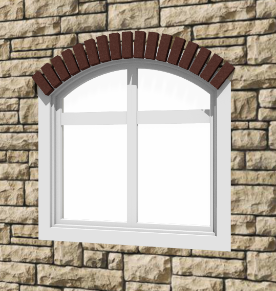
- Finally, use the Shift key on the keyboard and click to select all of the solids for both the brick and mortar, then click the Make Architectural Block edit button to group all of these elements together.
If you will frequently be needing an arched soldier course of this size, you may also want to use the Add to Library edit tool with the Architectural Block selected to add it to the User Catalog for future use.
-
Lastly, take a Camera
 view to see the results.