QUESTION
When I place doors into a concrete garage curb, stem wall, or pony wall, I typically make the opening in the concrete larger than the doors framed rough opening. How can I do this in Chief Architect?
ANSWER
You can specify the desired size of a door's concrete cutout and then modify the framing around the door manually within a Wall Detail view.
To specify the default concrete cutout size for doors
- In your desired plan, select Edit> Default Settings
 from the menu.
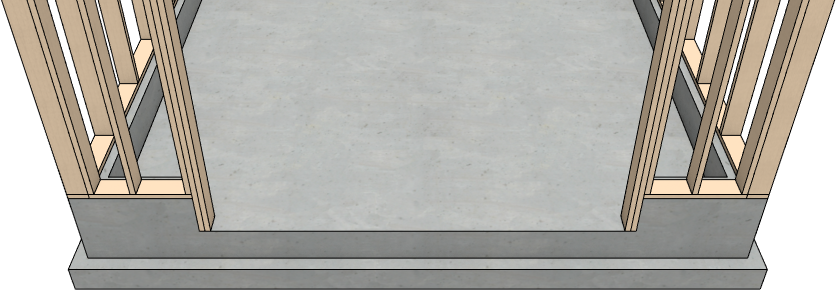
In this example, a simple rectangular garage structure with a stem wall foundation is used.
- In the Default Settings dialog, expand the Doors category, select your desired door default, then click the Edit button.
In this example, the Garage Door Defaults is selected for editing.
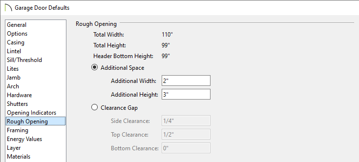
- On the Rough Opening* panel of the Garage Door Defaults dialog:
*Applies to X14 and newer program versions. Rough opening properties for X13 and prior versions can be specified on the Framing panel.
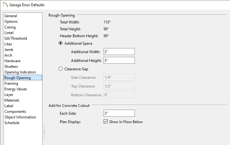
- In the Add for Concrete Cutout section, specify the amount to add to Each Side of the door opening when the upper part of the door is in a framed wall and the lower part is located in a concrete wall, stem wall, or garage curb.
- Uncheck Show In Floor Below to suppress the display of the concrete cutout in plan view.
In X15 and prior versions, this setting was called Show in Plan.
In this example, 3" is used, which will accommodate two trimmers (jack studs) on each side of the garage door.
- On the Framing panel:
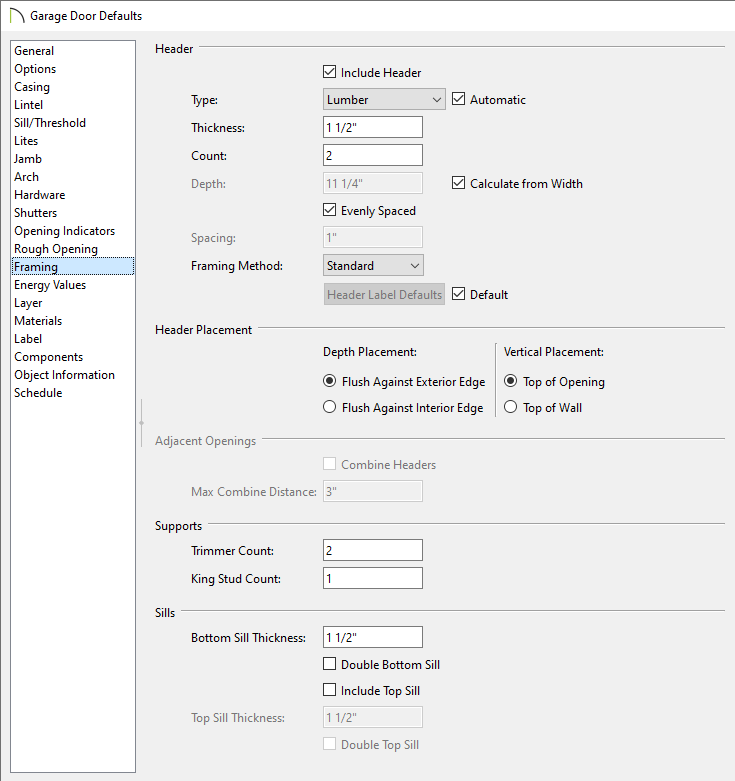
- Specify the Header Type, Thickness, Count, Depth, Spacing, and Framing Method*.
Keep Calculate from Width checked if you want the Header depth determined by the width of the door. The Calculate from Width settings are located in the Framing Defaults.
When Evenly Spaced is checked, the boards that comprise the header are evenly spaced within the wall's framing layer. Uncheck this box to specify the spacing of the header boards.
*Applies to X16 and newer program versions. In X15 and prior versions, a box header can be specified by checking the Box Header box.
- Specify the Depth and Vertical Placement options. If the Vertical Placement is set to Top of Wall, the Combine Headers box can be checked and a Max Combine Distance value can be specified.
- Specify the Trimmer Count and the King Stud Count*.
*Applies to X14 and newer program versions.
- Specify any properties related to Sills.
- Specify any other settings, then click OK to apply your settings.
- Click Done, then repeat Steps 3 - 4 for any other door defaults that need to be modified in this way.
To edit framing around a door
It's important to make sure a foundation is built before generating wall framing. To build a foundation, navigate to Build> Floor> Build Foundation.
- If you have not done so already, go ahead and generate wall framing in the plan.
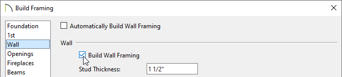
- Navigate to Build> Framing> Build Framing
 .
.
- In the Build Framing dialog that displays, check the Walls box under the Automatically Rebuild Framing or Build Framing Once section, then click OK.
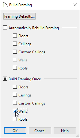
In X15 and prior versions, access the Wall panel, check either the Automatically Build Wall Framing or Build Wall Framing box, then click OK.
- A message may ask if you want to turn on the display of framing layers. Click Yes to turn on the associated framing layer(s) in floor plan view, or No to leave them turned off. Regardless of your choice, wall framing will be built.
- Using the Select Objects
 tool, click on a door to select it, then click the Open Object
  edit button.
- On the Rough Opening* panel of the Door Specification dialog, take note of the Total Height value listed, then click OK.
In X14 and prior program versions, this value isn't listed. Instead, take note of the Top and Bottom values, as well as the door's Height listed on the General panel, then combine them together to obtain the total height.
*Applies to X14 and newer program versions. Rough opening properties for X13 and prior versions can be specified on the Framing panel.
- Next, click on the wall that has a door with framing that you want to edit to select it, then click the Open Wall Detail
 edit button.
- Select one of the door trimmers and click the Open Object edit button. On the General panel of the Framing Specification (Trimmer) dialog:
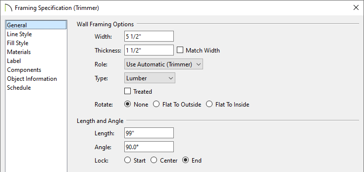
- Click the radio button beside Lock End to prevent the top edge of the selected trimmer from moving.
- Specify the Length as the total noted for the door in Step 3, above.
In this example, we will be specifying a value of 99".
- Click OK to close the dialog and apply your change.
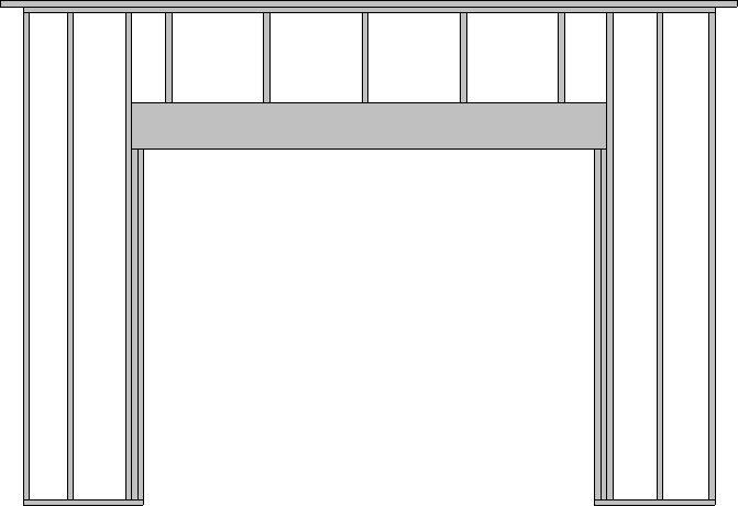
- Notice that the selected trimmer is now longer than the others.
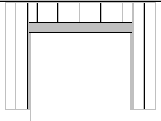
- Repeat Step 5 to lengthen all of the trimmers as needed.
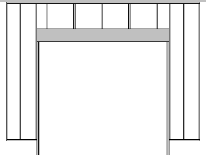
- Select each of the bottom plates and adjust them to your liking, making sure that they snap to the studs.
If you have trouble adjusting the plates or studs, ensure that Object Snaps are enabled by navigating to Edit> Snap Settings, then reattempt to adjust the framing members.
- Close the Wall Detail window, then create a Framing Overview
 to see the results.