QUESTION
I need to manage or create a particular line style in my drawing. How can I do this?
ANSWER
Access the Line Style Management dialog to manage line styles located within an existing plan or layout, as well as create new line styles. Additionally, line styles can be created directly from the User Catalog section of the Library Browser.
Managing line styles
- Select CAD> Lines> Line Style Management
 from the menu.
- In the Line Style Management dialog:
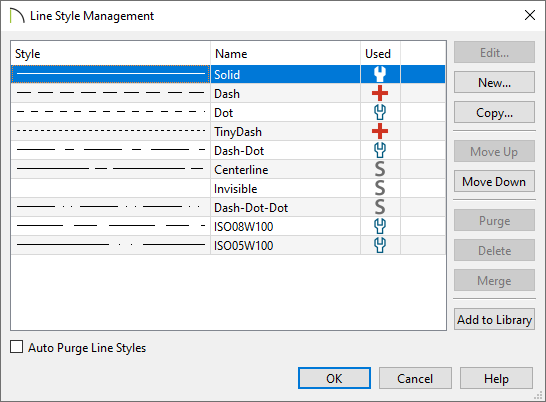
- Click on Edit if you would like to modify the line style you have selected.
- Click on New to bring up a dialog to create a line style.
- Use the Copy button to make a duplicate of the line style you have selected.
- The Move Up and Move Down buttons will move the selected line style up or down one position in the list.
-
Purge will delete any unused line styles in the current plan file.
-
Delete will remove the selected line style from the list.
- Select two or more line styles and click the Merge button to keep the topmost selection and delete the other(s). Any instances of the deleted line styles in the current file with replaced by the remaining style. A system default line style can only be part of a merge if it is the topmost selection and no other system line styles are included in the selection.
- Click Add to Library to add the selected line style to the User Catalog to be used in future plans.
- When Auto Purge Line Styles is unchecked and all instances of a line style are removed from the current file, it will continue to be saved in the file and listed here. Check this box to remove unused line styles from the file.
To create a custom line style
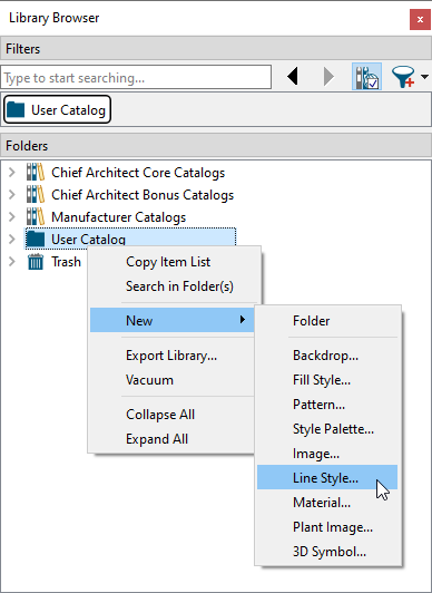
- Select CAD> Lines> Line Style Management , then click on New as mentioned in the section above, or right-click on the User Catalog folder located in the Library Browser
 and select New> Line Style.
- In the Line Style Specification dialog, type a short, descriptive Line Style Name for the line style.
In this example, "Grey Water (large)" is specified.
- Next, insert a line style component: a Dash, Dot, or Text item.
In this example, a total of four components are used: three Dash components and one Text component.
- With each component created, the characteristics of each can now be adjusted. To select a component, click on it in the line style preview diagram or in the list of components located to the right of the Insert options.
In this example, the three Dash components have a Length and Spacing value of 1/8", while the Text component has a Length of 43/128", a Spacing and Text Height of 1/8", and the Text of G/W.
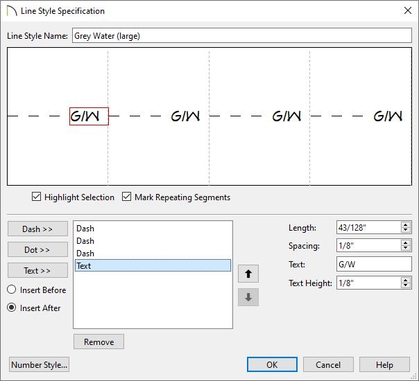
- When you are satisfied with the appearance of the line style in the preview diagram, click OK to close the dialog and apply your changes.
You can make changes to this line style's attributes at any time by right-clicking on its name and selecting Open Object  from the contextual menu.
- There are several ways to use your new custom line style:
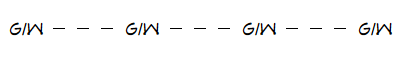
- Click on the line style in the library, move your mouse pointer into the drawing area, then click-and-drag to draw a CAD line.
- Assign the line style to any object on the Line Style panel of the object's Specification dialog.
- Assign the new line style to the Current CAD Layer
 and all CAD objects will be drawn using that line style.
- Assign the new line style to any layer of your choice using the Layer Display Options
 dialog or Active Layer Display Options
  side window.
When a line style with text is used in a drawing, its font, style, and transparency will be determined by the Text Style assigned to the layer that the object using that line style is on.