QUESTION
How do I create and generate framing for a parapet wall that has an arch?

ANSWER
You can create an arched parapet wall by building a new 2nd floor, adjusting the height and materials as needed, and then modifying the front parapet wall using a roof plane.
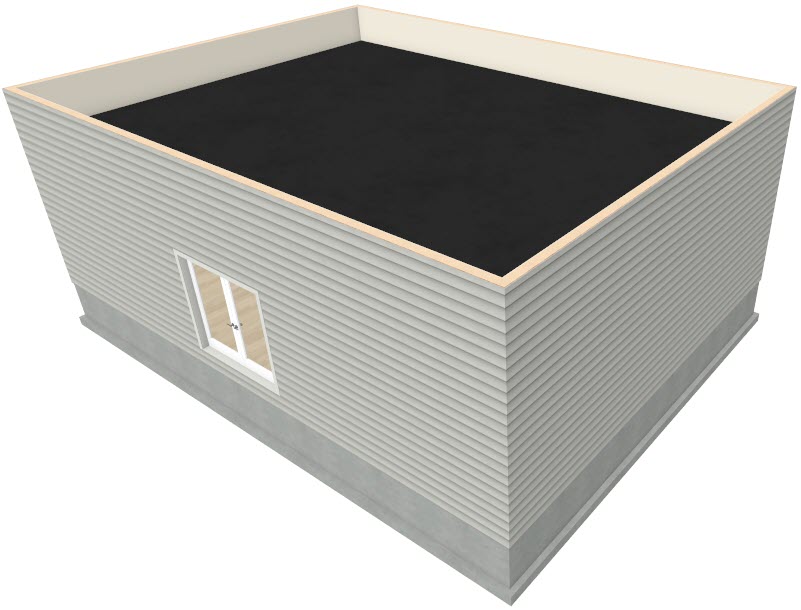
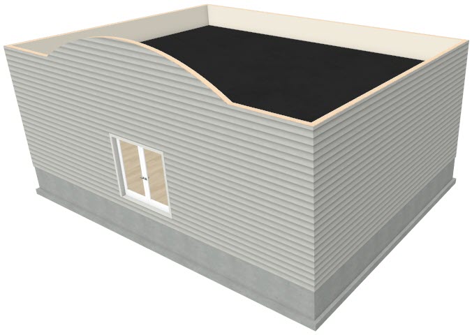
Begin by opening the plan in which you would like to create an arched parapet wall. In this example, a simple 30' x 40' rectangular structure with a basic foundation will be used.
To create parapet walls
- The roof area with parapet walls will be created using an additional floor, so select Build> Floor> Build New Floor
 from the menu.
- In the New Floor dialog, choose Derive new 2nd floor plan from the 1st floor plan option and click OK
- On the Structure panel of the 2nd Floor Defaults dialog, which opens next:
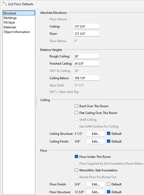
- Set the Rough Ceiling value to equal the height you would like your parapet walls to be.
In this example, a value of 36" is specified.
- Remove the checks from Roof Over This Room and Flat Ceiling Over This Room.
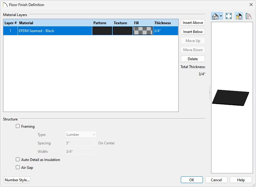
- Click the Edit button next to Floor Finish to open the Floor Finish Definition dialog.
-
Select the topmost layer, click in the Texture box, select an appropriate flat roofing material, then click OK.
-
Add and/or remove any additional layers, as desired.
-
Click OK.
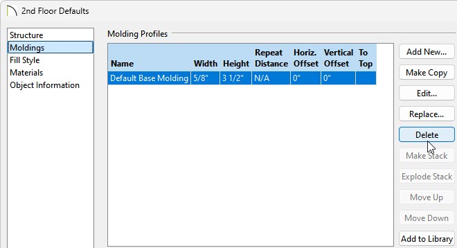
- Next, access the Moldings panel and click on the Delete button to remove the base molding from the 2nd floor.
- Click OK, then create a Camera
 view to see the results so far.
To add an arch to a parapet wall
- Using the Select Objects
 tool, click on the 2nd floor parapet wall that will have an arch, then click the Open Object
  edit button.
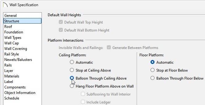
- On the Structure panel of the Wall Specification dialog that displays, select the Balloon Through Ceiling Above option under the Ceiling Platform heading, then click OK.
- Select Build> Roof> Roof Plane
 from the menu and perform the following:
- Left-click and drag to create the roof plane's baseline spanning both the interior and exterior of the parapet wall.
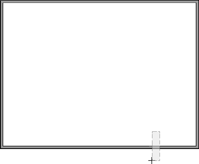
- Once the baseline has been created, move the mouse to the opposite side of the structure and click where you would like the roof plane to stop at.
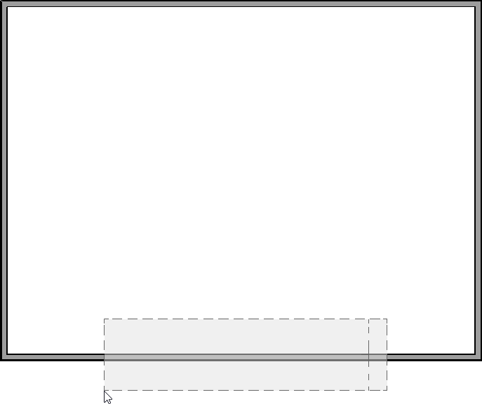
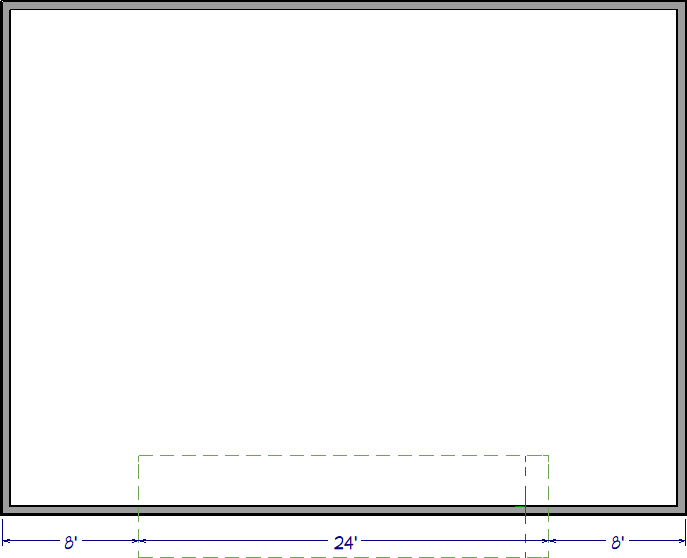
- Adjust the left and right edges of the roof plane, as needed. The left edge of the roof plane will be where the arch starts, while the right edge will be where the arch stops.
In this example, we created a roof plane that is 24' in length and centered on the structure.
- Select the roof plane and click the Open Object edit button.
- On the General panel of the Roof Plane Specification dialog:
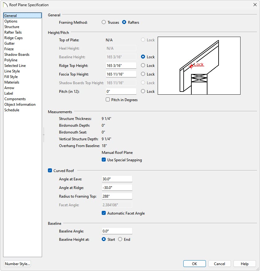
- Specify a value of 0" in the Pitch input field.
- Check the box beside Curved Roof.
- Set the Angle at Eave value to 30°.
-
On the Structure panel, uncheck the Use Room Ceiling Finish box located under the Roof Layers heading.
- Click OK to close the dialog and apply your changes.
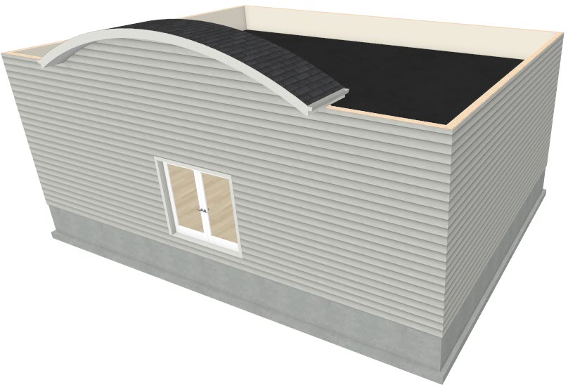
- Create a Camera view to see the results so far.
- Next, while remaining in the camera view, open the Layer Display Options dialog by navigating to Tools> Layer Settings> Display Options
 , or access the Active Layer Display Options
  side window.
![]()
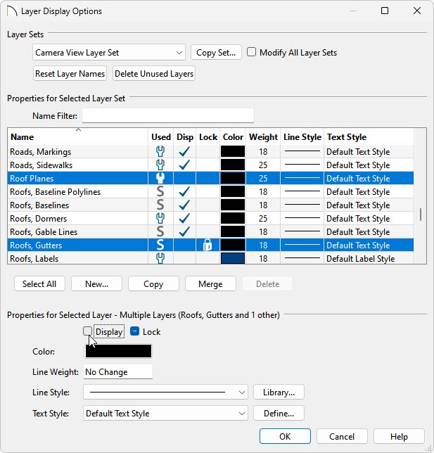
- Scroll down the list of layers to find the "Roof" layers or use the Name Filter to filter by keyword.
- Turn off the display of the "Roof Planes" and the "Roofs, Gutters" layers.
- Click OK.
- If wall caps are desired, select the 2nd floor walls using the Select Objects tool, click the Open Object edit tool, and on the Wall Cap panel of the Wall Specification dialog that appears:
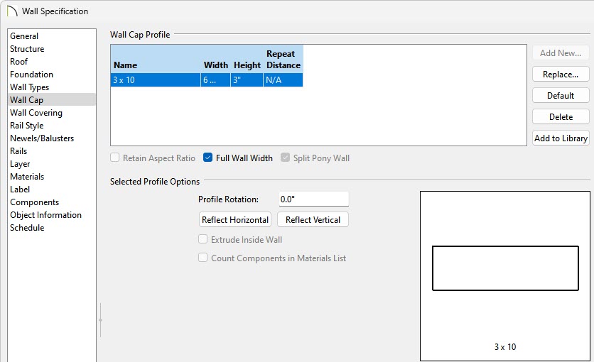
- If necessary, uncheck the No Change box.
- Click the Add New button to browse the library for a suitable profile, then click OK.
A variety of wall cap profiles can be located by navigating to Chief Architect Core Catalogs> Architectural> Moldings, Profiles, Extrusions> Handrails and Caps, and Sills and Caps.
- Make any desired adjustments to the Width and Height, then click OK.
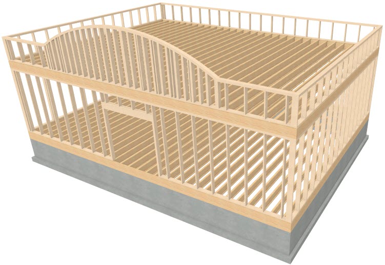
To build framing*
*Applies to Chief Architect Premier only.
- In a floor plan view, select Build> Framing> Build Framing
 from the menu.
- In the Build Framing dialog that displays, check the Floors, Ceilings, and Walls boxes under the Automatically Rebuild Framing or Build Framing Once section, then click OK.
In X15 and prior, access each of the various dialog panels, check the appropriate Build Floor/Ceiling Framing and Build Wall Framing boxes, then click OK.
- Navigate to 3D> Create perspective View> Perspective Framing Overview
 to see a camera view of the framing.