QUESTION
I want to add spiral HVAC ductwork and vents to my plan. How can I do this?

ANSWER
With the HVAC No.2 Spiral Ducting bonus catalog, spiral HVAC ductwork can be easily drawn into any plan as CAD lines or polylines, then converted to a special molding profile.
An active software subscription or active Support and Software Assurance (SSA) is required to access additional catalogs, such as the bonus catalog above. If you don't have access to the catalog above, please contact our Sales team to discuss your options.
For more information on accessing additional catalogs, please see the "Obtaining and Updating Library Content" resource in the Related Articles section.
To draw spiral HVAC ductwork
-
From the menu, select CAD> Lines> Draw Line
 and draw a line or polyline where you want your ducts to be.
-
Select the line or polyline, then click the Convert Polyline
 edit button.
-
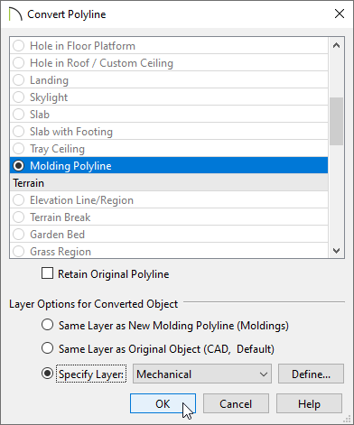
In the Convert Polyline dialog that appears, select the Molding Polyline option, choose your desired layer option, then click OK.
-
In the Molding Polyline Specification dialog that appears:
-
On the General panel, set the Height, or elevation, of the duct. Remember that the molding generates up, so the height will be the measurement from the top of the unfinished floor to the bottom of the duct.
In this example, a value of 117" is specified.
-
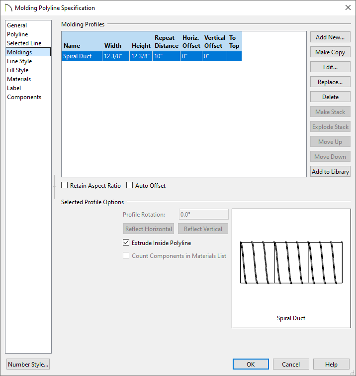
Select the Moldings panel and click the Replace button. Browse to Chief Architect Bonus Catalogs> HVAC No.2 Spiral Ducting, select the Spiral Duct option, then click OK.
-
Specify the molding profile's Width and Height as necessary, then click OK.
-
Repeat this as necessary for any additional ducts needed. It is not necessary at this time to butt or link the moldings together at intersections, as special connectors will be used to cover these areas.
To place duct fittings
Duct transitions, reducers, and vents are available as 3D Symbols that can be placed to create a more accurate representation of how your ducting will be built.
-
From a plan view, open the Library Browser
 , browse into Chief Architect Bonus Catalogs> HVAC No.2 Spiral Ducting, and select the symbol you wish to place.
In this example, we will be using the Cross fitting found within the 90 Degree Transitions subfolder.
-
Click to place the fitting. If necessary, you can temporarily disable snap settings by holding the Ctrl/Command key on your keyboard while placing the fitting.
-
Using the Select Objects
 tool, click on the fitting to select it, then click the Open Object
  edit button.
-
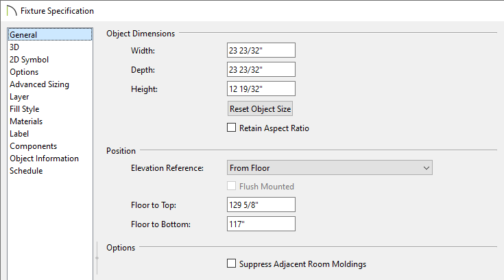
On the General panel of the Fixture Specification dialog that displays:
-
Set the Width, Depth, and Height, as needed.
For these types of symbols, if the size of the duct was modified, it's best to check the Retain Aspect Ratio check mark before making any modifications.
- Set the Elevation Reference to From Floor, then specify the Floor to Bottom value to match the height of the molding polyline.
In this example, a value of 117" is specified.
-
Click OK to confirm the changes and close the dialog.
-
Repeat this process to place as many fittings as necessary.