Creating CAD Details


Reference Number: KB-00766
Last Modified: July 15, 2021

The information in this article applies to:

Premier


QUESTION

How can I create, or find, CAD details?

CAD detail of a crawl space


ANSWER

Chief Architect provides several methods to create CAD details:

  • The Auto Detail tool is available in cross section/elevation views and quickly adds basic concrete, wall insulation, and siding patterns to the view, all with a single click.

  • The CAD Detail From View tool converts the current view into a 2D CAD drawing composed of editable CAD objects. This tool does not modify the original view the CAD Detail was created from.

  • The CAD Blocks folder located in the library includes a selection of blocked detail drawings and components that can be placed and used as they are, or edited to meet your needs. 

    A bonus catalog titled CAD Blocks and Details is also available for download if your SSA (Support & Software Assurance) is active.

    Note: For more information on downloading and importing additional libraries, please see the "Obtaining Library Content" resource in the Related Articles section below. 

  • Using the various CAD tools, you can create your own details from scratch.

These tools and resources can be used singly or you may choose to use a combination of them. For example, there may already be a detail located in the CAD Blocks library folder that meets your needs. Or, you may instead want to create a section view based upon your existing project, have Chief Architect auto detail it, and then add any finishing touches using the various CAD tools.

In this article, we will provide an overview of the tools and resources mentioned above, including:


To create a cross section view

  1. In a plan file, select 3D> Create Orthographic View> Cross Section/Elevation View  or Backclipped Cross Section .


  2. With the tool selected, click and drag to create a section view. Where you click sets the location that the camera is placed, while the direction you drag determines the direction the section view will face.


  3. While the section view is active, navigate to Tools> Layer Settings> Display Options  or access the Active Layer Display Options  side window, and turn layers on/off, as necessary.

    To learn more about layers and how they're used in Chief Architect, please see the Related Articles section below.


To use the Auto Detail and CAD Detail From View tools

  1. While in a cross section/elevation view, navigate to CAD> Auto Detail to automatically generate concrete fill, wall insulation, and siding patterns for the view.

    If the Auto Detail option is grayed out, it signifies you're in a view that is not compatible with the tool. For example, Auto Detail is not available for Wall Elevations.

    For more information on the Auto Detail tool, please access your program's Help documentation.


  2. To make further CAD modifications, it is recommended to generate a CAD detail based upon the section view. Navigate to CAD> CAD Detail From View  from the menu.

    A CAD detail window will open and the view will now consist of editable CAD components.

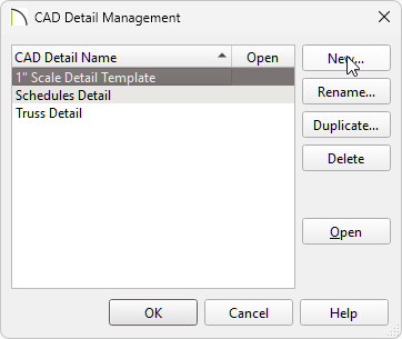
    Note: You can access this view at anytime by accessing the CAD Detail Management dialog, along with the CAD Details folder located in the Project Browser side window. Please see the next section in this article on accessing the CAD Detail Management dialog or see the Related Articles section for more information on using the Project Browser.

    The CAD Detail From View tool can also be used to generate a CAD detail from a floor plan view or from a 3D camera view using the Vector View rendering technique.


To place CAD from the library

  1. Select CAD> CAD Detail Management from the menu.


  2. In the CAD Detail Management dialog that opens, select the CAD detail you would like to modify, then click Open.

    If you haven't created a custom CAD detail, select the New button, specify your desired name, then click OK to create a new, blank CAD detail.

    Note: If you used the CAD Detail From View tool to create a CAD detail, the view will be listed here, and its name will reference the type of view it was created from.

    Creating a New CAD detail in the CAD Detail Management dialog


  3. With the CAD detail open, select View> Library Browser to open the Library Browser side window, if it's not already open.  

    • In the library, browse to Chief Architect Core Catalogs> CAD Blocks where a selection of CAD components are available.

      If you have downloaded the CAD Blocks and Details bonus catalog, you can also browse to Chief Architect Bonus Catalogs> CAD Blocks and Details to locate additional CAD components.

    • Click on a component to select it.

      In this example, the Concrete Footing is used, which is available by navigating to Chief Architect Core Catalogs> CAD Blocks> Detail Components> Footings & Slabs. 

    • When you move your cursor into the drawing area, it displays the CAD Block icon. Click once to place the selected CAD block in your CAD detail window.    

      Concrete block footing 8 inches by 16 inches


  4. In order for this item to be in the library, it was specified as a CAD block. To edit each component related this CAD block, enable the Select Objects tool, click on the footing to select it, then click the Explode CAD Block edit button.

    In X13, the ability to edit a CAD block in its own window was introduced. If you wish, you can edit the CAD block in a separate window using the Edit CAD Block  edit tool.

    To learn more about editing CAD, please see the next section in this article.


  5. Once you are done making modifications, group select all of the CAD objects, then click the Make CAD Block  edit button to block them back into a single entity.

    If you're using the Edit CAD Block tool in X13 and newer program versions, click Save Active View  . You may be prompted with a Question dialog asking if you'd like to replace all instances of the block with the copy you have modified. Choose your desired option to proceed.

    Note: For more information on group selecting objects, please see the appropriate resource in the Related Articles section below. 

  6. With the block selected, click the Add to Library   edit button to add the CAD block to the library for future use.


To draw and edit CAD


Depending on your requirements for a particular detail drawing, you may find that you use all of the CAD tool families: Lines, Arcs, Splines, Boxes and Circles. Two of the most common tools; Rectangular Polyline and Box, seem very similar at a glance, but are actually quite different from one another.

Rectangular Polylines
are composed of lines, just as their name implies, so each of their edges can be edited in the same way that lines can: they can be broken, trimmed, curved, deleted and so on.

Boxes are always closed shapes with four 90 degree corners. Their corners can be filleted or chamfered but their edges cannot be extensively edited. Boxes are useful when the item being drawn needs to remain a closed shape with right angles. For this reason, the Cross Box , Blocking Box ,and Insulation tools are considered boxes. 

  1. Select CAD> Boxes> Rectangular Polyline from the menu, then click and drag to create a rectangle.   

    • Don't worry about the exact size or location as you draw it: instead, use Temporary Dimensions  to resize it precisely once it is drawn.


  2. Using the Select Objects  tool, click on the rectangular polyline, then click the Open Object edit button. In the Polyline Specification dialog that displays:
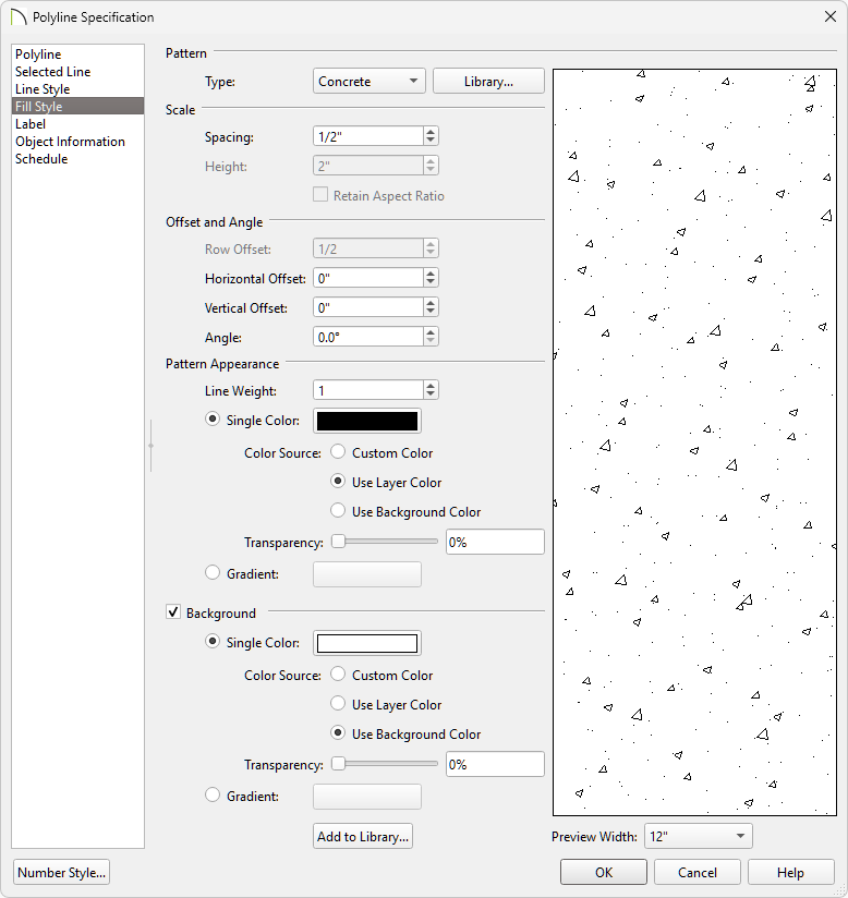
    Changing the Fill Style of the CAD polyline

    • On the Line Style panel, select a Color, Style, and Weight for the polyline.

    • On the Fill Style panel, specify the desired Pattern Type, along with any other settings.

    • Click OK to close the dialog and apply your changes.


  3. To edit the shape of a polyline or other CAD components, use the various edit tools that display in the Edit toolbar when a CAD object is selected.

    • Use the Break  edit tool to place additional break points, giving you additional edges that can be adjusted.

      If you want to add more than one break at a time, click the Sticky Mode secondary edit tool after the Break tool is selected.

    • Use the Change Line/Arc  edit tool to convert straight edges to curved, or vice versa.

    • Use the Chamfer  and/or Fillet edit tools to create a chamfer or fillet effect on each corner.

    • Use the Trim  and Extend Objects edit tools to shorten or lengthen components.


  4. Circles, which are useful for representing rebar, can be created by navigating to CAD> Circles> Circle .


  5. Select CAD> Boxes> Cross Box to create framing components, and CAD> Boxes> Insulation to add additional sections of insulation in floors or walls, as necessary.


  6. Navigate to CAD> Lines> Draw Line to draw CAD lines, or open polylines. Lines work great to represent grade lines or break lines.


  7. Use the Dimensions  and Text  tools to add annotations to your detail.


To accurately position CAD

In Chief Architect, there are a number of ways to position objects precisely. When preparing a detail drawing, three of the most useful techniques and tools are CAD Stops Move, Point to Point Move, and Transform/Replicate Object.


CAD Stops Move
is a setting found on the Line Style panel of the specification dialogs of Text and closed CAD objects such as circles, polylines, and boxes.

  • Check this box to enable this behavior for the selected object, and it will bump against other open and closed CAD objects when it is being moved, preventing them from overlapping.   

  • A quick way to align text objects is to draw a line and then, after checking CAD Stops Move in the text object's specification dialog, move the text so that it stops against the line, which can later be deleted.  

    Text objects stopped at a CAD line


To learn how to use the Point to Point Move edit tool, see the "Using the Point to Point Move Tool" resource in the Related Articles section below.
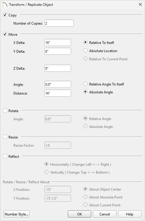
Use the Transform/Replicate Object tool to copy, move, rotate, resize, and reflect objects.

  1. Using the Select Objects  tool, click on a CAD object you'd like to modify, then click the Transform/Replicate Object  edit button. 

    This tool can also be used on objects that have been group selected. For example, if you'd like to rotate multiple objects all at once, using the Transform/Replicate Object tool may be the most efficient method.

      
  2. In the Transform/Replicate Object dialog that displays:   

    Transform/Replicate Object dialog where modifications can be made

    • Check the box beside Copy and specify the number of copies you want to make.  

    • Check the box beside Move and specify the increments that you want the copies to be placed on the appropriate Delta, or axis.  

    • Check Rotate if you'd like to rotate the objects, check Resize to specify a Resize Factor, or check Reflect to mirror the object.

    • Once your desired changes are made, click OK to close the dialog.


To add CAD to the library

  1. Group select the CAD components that you would like to add to the library, then click the Make CAD Block edit tool.

    For more information on group selecting objects, please see the appropriate resource in the Related Articles section below.


  2. Select the CAD Block, then click the Add to Library edit button to add the block to your Library Browser, where you can then rename it and move it into an appropriate folder in the User Catalog.

    Starting in X13, you can edit CAD blocks directly from the User Catalog. To do so, access the User Catalog, right-click on the CAD block you'd like to modify, then select Edit CAD Block  from the contextual menu that appears.

    Note: On a Mac, hold down the Control key while clicking to initiate a right-click command. More information about right-click commands on Apple input devices can be found in the following Apple resource: Right-click on Mac.