QUESTION
I need to create a custom object, what tool should I use?

ANSWER
A 3D Solid, also known as a Polyline Solid in X13 and prior versions, is a generic, 3D shape that has a specified thickness. They can be oriented either horizontally or vertically and are useful for creating custom details anywhere in your 3D model.
A horizontal 3D Solid can be created in floor plan view, or any 3D view, by selecting the 3D Solid tool and then clicking and dragging to draw a rectangle. In X13 and prior versions, you can select the Polyline Solid tool instead. A vertical 3D/Polyline Solid can be created in a cross section/elevation view in the same manner as in floor plan view. The 3D/Polyline Solid is placed in front of any objects visible in the view. If no objects are behind, the 3D/Polyline solid is placed one foot in front of the camera.
3D/Polyline Solids can be edited the same way as other closed polyline-based objects.
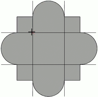
In this article, a custom shaped mirror will be created.
To create and edit the shape of a 3D/Polyline solid
- From the menu, select 3D> Create Orthographic View> Cross Section/Elevation
 and create an elevation view.
In this example we are working in a new, blank plan.
- From this new elevation view, select Build> Primitive> 3D Solid
 , then click and drag to create a rectangular 3D Solid.
In X13 and prior versions, navigate to Build> Primitive> Polyline Solid  instead.

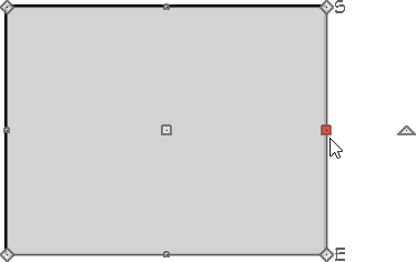
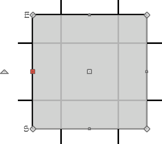
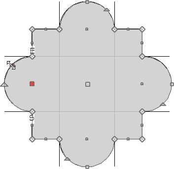
- Click on one side of the rectangle to activate that side. Notice that the edit handle on that side is now larger than the other sides. The active side is the side that will move when modifying dimensions.
The active edit handle can be a different color than the rest. By default, the handle will be red, but it can be changed on the Colors panel that's located in the Preferences dialog.
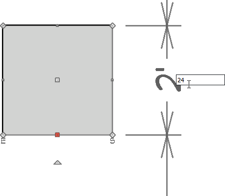
- Use temporary or manual dimensions to resize the rectangle to a basic 24" by 24" square.
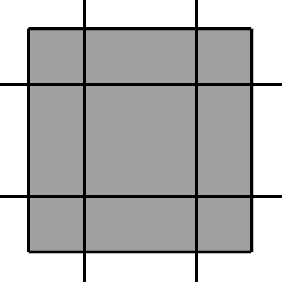
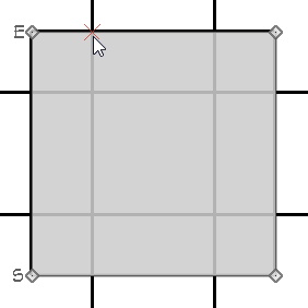
- Next, click CAD> Lines> Draw Line
 , then click and drag to draw four lines across the square 6" from the sides as shown:
- With the Select Objects
 tool active, select the 3D/Polyline Solid.
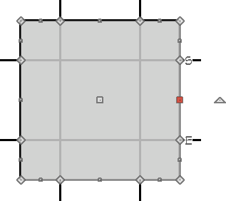
- On the Edit toolbar, click the Add Break
 tool and use the Intersections
  snap indicator to help place breaks points precisely where the lines intersect the 3D/Polyline Solid.
- Continue making break points at all intersections.Select the Sticky Mode
 secondary edit tool if you'd like to place multiple break points without having to re-select the Add Break tool each time.
- Using the Select Objects tool, select the top edge of the 3D/Polyline Solid and click the Change Line/Arc
 edit button, then use the small triangular edit handle on the edge of the arc to increase the arc's height until it is 6" tall.
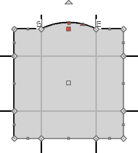
- Continue using the Change Line/Arc edit button to convert the middle sections of each side to arcs of 6" in height.
To create a hole in the 3D/Polyline solid
- Select CAD> Circles> Circle
 from the menu, and using the CAD line intersections within the 3D/Polyline Solid, click and drag to draw a circle.
- Select the CAD circle and then click the Convert Polyline
 edit button.
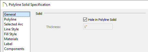
- In the Convert Polyline dialog, select 3D Solid Hole option and click OK.
In X13 and prior versions, select Polyline Solid instead, then click OK.
- In X13 and prior versions, on the General panel of the Polyline Solid Specification dialog, check the Hole in Polyline Solid box, then click OK.
A hole can also be created by first selecting the 3D/Polyline Solid, selecting the 3D Solid Feature/Create Hole edit tool, then clicking and dragging inside the solid.
To edit the thickness and material
- Using the Select Objects tool, select the main 3D/Polyline Solid, then click the Open Object
 edit button.
- In the 3D/Polyline Solid Specification dialog that opens:
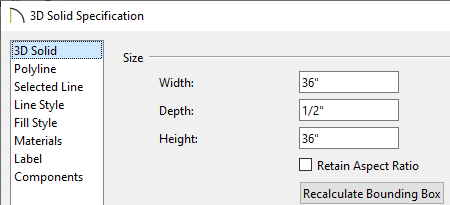
- In X14 and newer versions, on the 3D Solid panel, set the Depth to 1/2".
In X13 and prior versions, on the General panel, set the Thickness to 1/2".
- On the Materials panel, select the 3D/Polyline Solid sub-component, click the Select Material button, then search for a Mirror material.
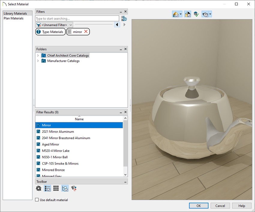
- Once the desired material is chosen, click OK and OK a second time to confirm the changes and close both dialogs.
To add the 3D Solid to your User Catalog
-
Using the Select Objects tool, select your 3D Solid and click on the Add to Library
 edit button to add the object to the User Catalog.
In X14 prior versions, the 3D/Polyline solid must be part of an architectural block before it can be added to the User Catalog. Please see the "Adding a 3D/Polyline Solid to the User Catalog" resource in the Related Articles section for more information.
- To use this 3D Solid in the future or in a different plan file, select it from your User Catalog and place it into your plan.
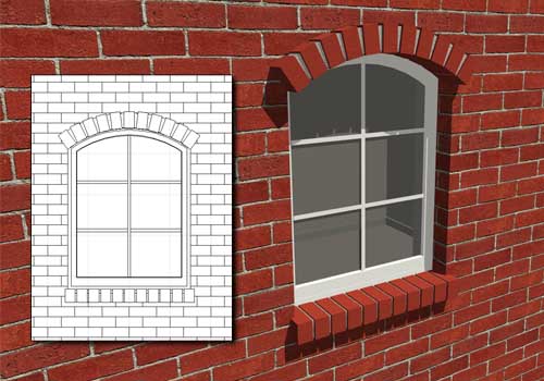
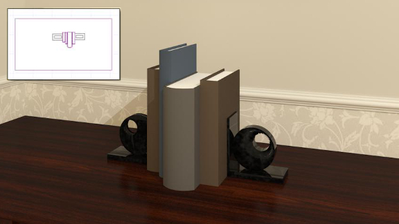
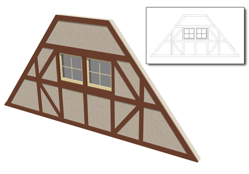
Additional examples created using 3D/Polyline Solids
- Bookends
- Gingerbread fachwerk architecture
- An arched soldier course