QUESTION
How do I control what part of a pony wall displays in a specific plan view, such as a Foundation Plan View?
ANSWER
Access the Plan View Specification dialog to change how pony walls are displayed for the active plan view. Choose from the following options: upper wall, lower wall, upper wall and lower wall outline, upper wall outline and lower wall, or upper wall and lower wall.
To change the display of pony walls in a plan view
-
Open
 the plan in which you want to change how pony walls display.
- Ensure the desired plan view is active, then navigate to Tools> Active View> Edit Active View
 from the menu.
- On the General panel of the Plan View Specification dialog that displays:
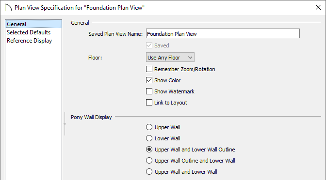
- Specify your desired option under the Pony Wall Display section.
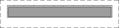
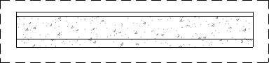
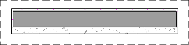
In this example, a Siding-6 wall type is specified for the upper portion of a pony wall, and a 8" Concrete Stem Wall wall type is specified for the lower portion. A concrete footing is also applied, which is represented by dashed lines.
-
Upper Wall displays the upper portion of the pony wall only.
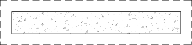
-
Lower Wall displays the lower portion of the pony wall only.
-
Upper Wall and Lower Wall Outline displays the upper portion of the pony wall in its entirety with an outline of the lower wall portion in the background.
-
Upper Wall Outline and Lower Wall displays the lower portion of the pony wall in its entirety with an outline of the upper wall portion in the foreground.
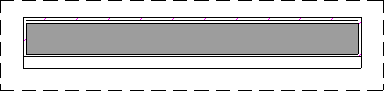
-
Upper Wall and Lower Wall displays both walls in their entirety, but the upper wall portion will display in the foreground.
- Click OK.
MORE INFORMATION
- By default, when a door or window is located entirely in one part of a pony wall, and that part is not displayed in plan view, the opening’s outline is shown but the wall’s layer lines and fill will be drawn through it. You can instead display openings in the non-displayed parts of pony walls the same as in the displayed parts, or not at all. Please refer to the Pony Wall Defaults section located in your program's Help documentation to learn more.
- The display of pony walls can also be controlled in the Pony Wall Defaults, or on a per wall basis by accessing the Wall Specification dialog.
- Foundation walls have footings that display in plan view as long as the “Footings” layer is turned on. Brick ledge lines can also display. In stem wall and grade beam foundations, brick ledge lines are on the “Slabs” layer. In monolithic slab foundations, they are on the “Walls, Foundation” layer.