A plumbing system is a network of pipes, fittings, fixtures, and valves that delivers water where needed throughout the home while safely removing wastewater. While often one of the more underappreciated and unnoticed parts of a house, a well-built plumbing system is critical in ensuring health and sanitation.
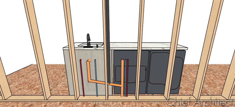
With potentially hundreds of feet of piping navigating through a home’s structure, envisioning how a plumbing system is built can be challenging. 3D plumbing isometrics solves this challenge by allowing designers and contractors to visualize in far greater detail how a plumbing system may come together. This can help avoid problems during construction by highlighting conflicts between the plumbing system and the home’s structural components. For example, by visualizing in 3D where the plumbing lines are running, you could easily recognize a scenario such as a floor joist interfering with the placement of a toilet flange and its respective wastewater lines. Identifying and correcting such conflicts in the design phase is faster, easier, and less expensive than correcting them in the field.
Additionally, many building departments are now requiring plumbing wastewater isometrics in order to obtain a building permit. We have noticed that some building departments have begun requiring isometric drawings for supply lines (water and gas) as well as drain and vent lines.
- What’s the difference between 3D plumbing and a plumbing isometric?
- Benefits of showing 3D plumbing and plumbing isometrics
- Creating 3D plumbing and plumbing isometrics in Chief Architect
What’s the difference between 3D plumbing and a plumbing isometric?
Traditional 2D plumbing plans typically show the location of plumbing fixtures and include 2D CAD lines that provide a general idea of plumbing connections (i.e., supply lines running from the source to the fixture). 3D plumbing and plumbing isometrics go beyond that by providing a visual 3-dimensional representation of what the actual system will look like as it runs through a home’s structure.
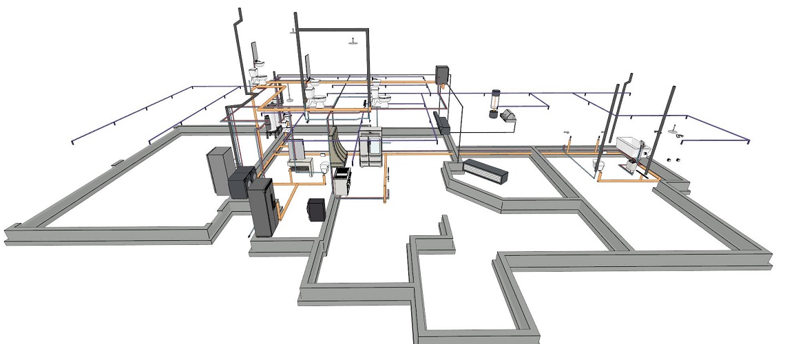
- 3D plumbing views will show how the entire plumbing system comes together, from the water traveling through the supply lines into the house, through walls, framing, etc., and finally to the fixtures where the water is needed and waste lines bringing water out of the house. By creating a 3D plumbing plan, you’ve created a synchronized model that is consistent between any views you create (floor plans, sections, orthographic views, etc.). This establishes an accurate basis for providing contractors and building departments with plumbing plans.
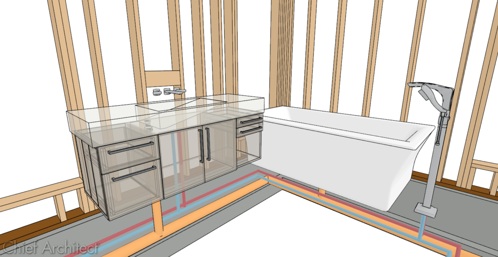
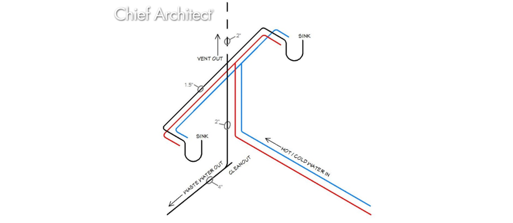
- A plumbing isometric is a diagram created from a 3D plumbing view highlighting key areas of the plumbing system. Plumbing isometrics can be notated with text notes, dimensions, and more to provide granular details about the system. For example, in a bathroom with a double vanity, a plumbing isometric may show the p-trap, drain line, and venting required for two sinks and may provide dimensions or text notes about the pipe size, connection types, waste line slopes, and more. This makes it easy to understand finer details about the plumbing system.
Benefits of showing 3D plumbing and plumbing isometrics
The end goal of providing 3D plumbing and plumbing isometrics is to provide a clear visualization of the plumbing system. This can help identify potential conflicts before the system is built, improve communication between contractors, or meet building department requirements.
- Identify Potential Conflicts
The process of creating 3D plumbing will help identify potential clashes between the plumbing components and other building components, such as framing, electrical, HVAC, etc., during the design phase (before construction begins). It is much more efficient and cost-effective to correct issues during design rather than having to rework things in the field.
- Improved Communication
Including 3D plumbing and plumbing isometrics in your plans will more precisely communicate how the different home systems are meant to be built. For example, by modeling how plumbing will route through framing, both the framer and plumber will clearly understand why their system is designed the way it is and how their respective work will interact with each other. This can help foster better communication between the trades and reduce the risk of misunderstandings.
- Meet Building Department Requirements
More and more building departments are requiring plumbing isometrics in order to obtain a building permit. Including 3D plumbing along with plumbing isometrics into your construction documents adds an additional level of detail that can help plan reviewers understand the plumbing system layout and assess critical factors such as the pipe size and slope, fixture placement, venting, etc. to ensure they are meeting building codes. This can help minimize any questions the building department may ask about the plumbing system design, saving you time and money while moving through the permitting process.
Creating 3D plumbing & Plumbing isometrics in Chief Architect
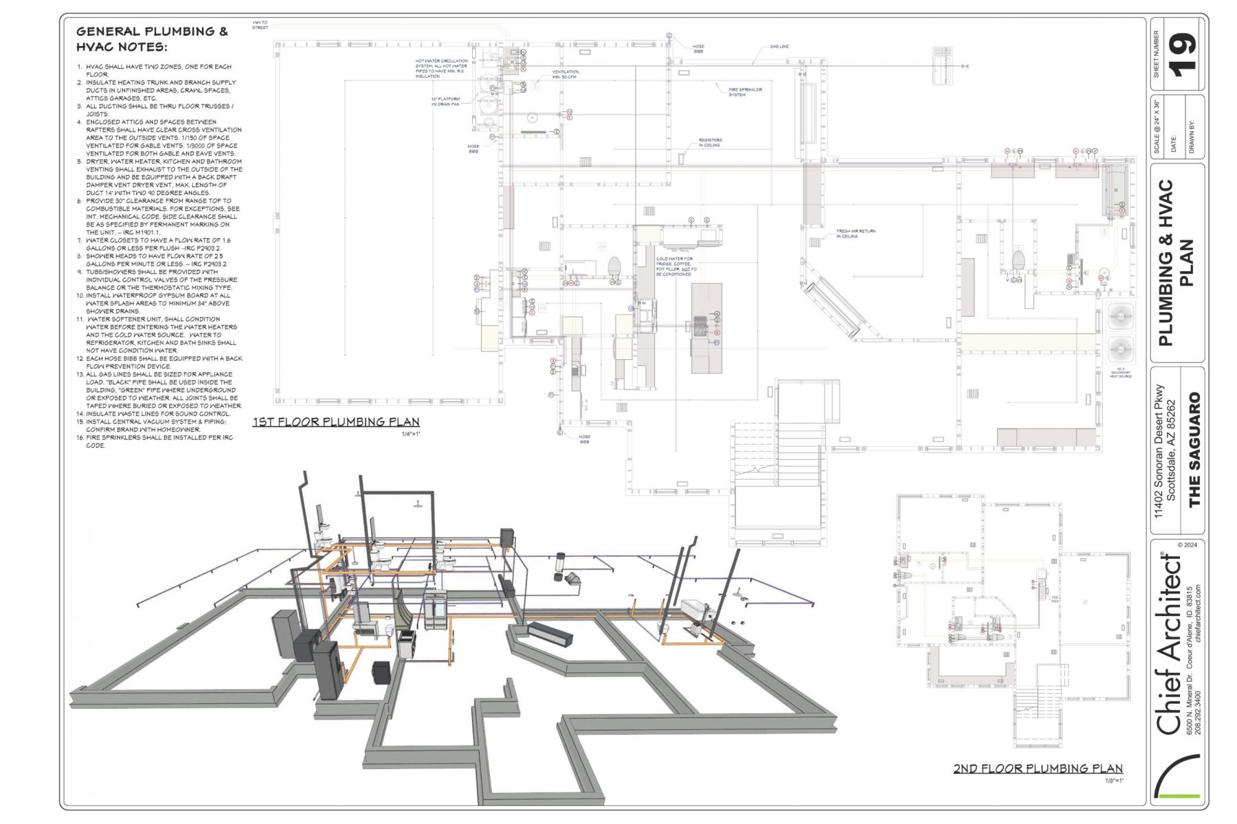
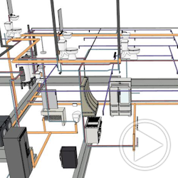
3D plumbing and plumbing isometrics can be designed in Chief Architect. Once your design is created, you will know the location of various fixtures, such as sinks, faucets, hose bibs, hot water heater, showers, etc. The various plumbing lines will be drawn using the Molding Polyline tool. You can create pipes of various sizes and color code them to represent wastewater lines, supply lines, etc. As you draw the 3D plumbing line, plumbing that conflicts with other building components (such as framing) becomes self-evident, and the best resolution can be determined and implemented into the plan. See an example of 3D plumbing in the Saguaro sample plan.
Plumbing isometrics are often more standardized and used to highlight how plumbing code will be met. In Chief Architect, you can create a plumbing isometric by taking an orthographic view of the 3D plumbing lines you’ve drawn, convert it to a CAD detail, notate it as needed, and use it in your construction documents or draw it in a plan view with the CAD tools. Because plumbing isometrics are more standardized, you can create the plumbing isometric once and save it for reuse in future plans. If minor changes are needed in a future project, you can quickly unblock the isometric CAD block and make the required edits.
Visualizing 3D plumbing and plumbing isometric is about unlocking a deeper understanding of the plumbing system and how it relates to other systems of a home, resulting in a properly built and safer home. Do you currently or plan to incorporate 3D plumbing isometrics in your home designs and blueprints? Let us know your thoughts in the comments!

 by
by 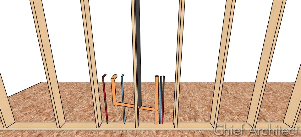


5 comments